
User`s manual


<2. Handling Cautions>
2-4
IM 01C25B01-01E
2.9.1 FM Approval
a. FM Intrinsically Safe Type
Caution for FM intrinsically safe type. (Following
contents refer “DOC. No. IFM022-A12”)
Note 1. Model EJX/EJA-E Series Differential,
gauge and absolute pressure transmitters
with optional code /FS1 are applicable for
use in hazardous locations.
• Applicable Standard: FM3600, FM3610,
FM3611, FM3810
• Intrinsically Safe for Class I, Division 1,
Groups A, B, C & D. Class II, Division 1,
Groups E, F & G and Class III, Division 1,
Class I, Zone 0 in Hazardous Locations, AEx
ia IIC
• Nonincendive for Class I, Division 2, Groups
A, B, C & D. Class II, Division 2, Groups F &
G, Class I, Zone 2, Groups IIC, in Hazardous
Locations.
• Outdoor hazardous locations, NEMA 4X.
• Temperature Class: T4
• Ambient temperature: –60 to 60°C
Note 2. Entity Parameters
• Intrinsically Safe Apparatus Parameters
[Groups A, B, C, D, E, F and G]
Vmax = 30 V Ci = 6 nF
Imax = 200 mA Li = 0 µH
Pmax = 1 W
* Associated Apparatus Parameters
(FM approved barriers)
Voc ≤ 30 V Ca > 6 nF
Isc ≤ 200 mA La > 0 µH
Pmax ≤ 1W
• Intrinsically Safe Apparatus Parameters
[Groups C, D, E, F and G]
Vmax = 30 V Ci = 6 nF
Imax = 225 mA Li = 0 µH
Pmax = 1 W
* Associated Apparatus Parameters
(FM approved barriers)
Voc ≤ 30 V Ca > 6 nF
Isc ≤ 225 mA La > 0 µH
Pmax ≤ 1 W
• Entity Installation Requirements
Vmax ≥ Voc or Uo or Vt, Imax ≥ Isc or Io or It,
Pmax (or Po) ≤ Pi, Ca or Co ≥ Ci + Ccable,
La or Lo ≥ Li + Lcable
Note 3. Installation
• Barrier must be installed in an enclosure that
meets the requirements of ANSI/ISA S82.01.
• Control equipment connected to barrier must
not use or generate more than 250 V rms or
V dc.
• Installation should be in accordance with
ANSI/ISA RP12.6 “Installation of Intrinsically
Safe Systems for Hazardous (Classied)
Locations” and the National Electric Code
(ANSI/NFPA 70).
• The conguration of associated apparatus
must be FMRC Approved.
• Dust-tight conduit seal must be used when
installed in a Class II, III, Group E, F and G
environments.
• Associated apparatus manufacturer’s
installation drawing must be followed when
installing this apparatus.
• The maximum power delivered from the
barrier must not exceed 1 W.
• Note a warning label worded
“SUBSTITUTION OF COMPONENTS MAY
IMPAIR INTRINSIC SAFETY,” and “INSTALL
IN ACCORDANCE WITH DOC. No. IFM022-
A12”
Note 4. Maintenance and Repair
• The instrument modication or parts
replacement by other than authorized
representative of Yokogawa Electric
Corporation is prohibited and will void
Factory Mutual Intrinsically safe and
Nonincendive Approval.
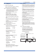
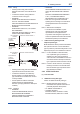
F0203-1.ai
Class I, II, III, Division 1,
Groups A, B, C, D, E, F, G
Class 1, Zone 0 in
Hazardous (Classified)
Locations AEx ia IIC
Pressure Transmitters
Safety Barrier
Supply
Hazardous Location Nonhazardous Location
General
Purpose
Equipment
+
–
+
–
+
–
+
–
[Intrinsically Safe]