
User`s manual


<5. Installing Impulse Piping>
5-2
IM 01C25B01-01E
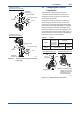
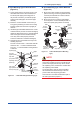
Pipe-Mounting Type 3-Valve Manifold
(Figure 5.2)
1) Screw nipples into the connection ports on the
transmitter side of the 3-valve manifold, and
into the impulse piping connecting ports on
the process connectors. (To maintain proper
sealing, wind sealing tape around the nipple
threads.)
2) Mount the 3-valve manifold on the 50 mm (2-
inch) pipe by fastening a U-bolt to its mounting
bracket. Tighten the U-bolt nuts only lightly at
this time.
3) Install the pipe assemblies between the 3-valve
manifold and the process connectors and lightly
tighten the ball head lock nuts. (The ball-shaped
ends of the pipes must be handled carefully,
since they will not seal properly if the ball
surface is scratched or otherwise damaged.)
4) Now tighten the nuts and bolts securely in the
following sequence:
Process connector bolts → transmitter-end ball
head lock nuts → 3-valve manifold ball head
lock nuts → 3-valve manifold mounting bracket
U-bolt nuts
F0502.ai
Nipple
Nipple
Process
connector
Ball head
lock nut
Pipe
Ball head
lock nut
Process
connector bolts
50 mm(2-inch) pipe
Pipes
3-valve
manifold
Impulse piping
Vent plug
(optional)
Stop valve
(low pressure side)
Equalizing valve
(balancing)
Stop valve
(high pressure side)
Figure 5.2 3-Valve Manifold (Pipe-Mounting Type)
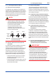
Direct-Mounting Type 3-Valve Manifold
(Figure 5.3)
1) Mount the 3-valve manifold on the transmitter.
(When mounting, use the two gaskets and the
four bolts provided with the 3-valve manifold.
Tighten the bolts evenly.)
2) Mount the process connectors and gaskets
on the top of the 3-valve manifold (the side on
which the impulse piping will be connected).
Bolts
Process
connector
Gasket
Gasket
Process
connector
Bolts
Stop valve
Stop valve
3-valve
manifold
3-valve
manifold
Equalizing valve
Equalizing
valve
Stop valve
Impulse
piping
Impulse
piping
Stop valve
F0503.ai
Figure 5.3 3-Valve Manifold (Direct-Mounting
Type)
NOTE
After completing the connection of the transmitter
and 3-valve manifold, be sure to CLOSE the low
pressure and high pressure stop valves, OPEN
the equalizing valve, and leave the manifold with
the equalizing valve OPEN.
You must do this in order to avoid overloading
the transmitter from either the high or the low
pressure side when beginning operation.
This instruction must also be followed as part of
the startup procedure (chapter 7.)