
User`s manual


<6. Wiring>
6-3
IM 01C25B01-01E
(2) Flameproof Type
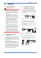
Wire cables through a ameproof packing adapter,
or use a ameproof metal conduit.
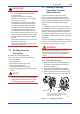
■ Wiring cable through ameproof packing
adapter.
• Apply a non-hardening sealant to the terminal
box connection port and to the threads on the
ameproof packing adapter for waterproong.
Flameproof packing
adapter
Flexible metal conduit
Wiring metal
conduit
Tee
Drain plug
Apply a non-hardening
sealant to the threads for
waterproofing.
F0609.ai
Figure 6.9 Typical Cable Wiring Using Flameproof
Packing Adapter
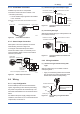
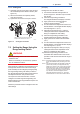
■ Flameproof metal conduit wiring
• A seal tting must be installed near the terminal
box connection port for a sealed construction.
• Apply a non-hardening sealant to the threads of
the terminal box connection port, exible metal
conduit and seal tting for waterproong.
F0610.ai
Non-hazardous area
Hazardous area
Flameproof
heavy-gauge
steel conduit
Tee
Drain plug
Seal fitting
Gas sealing device
Flameproof flexible
metal conduit
Apply a non-hardening
sealant to the threads of
these fittings for
waterproofing
After wiring, impregnate the fitting
with a compound to seal tubing.
Figure 6.10 Typical Wiring Using Flameproof Metal
Conduit
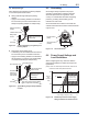
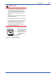
6.5 Grounding
Grounding is always required for the proper
operation of transmitters. Follow the domestic
electrical requirements as regulated in each
country. For a transmitter with a built-in lightning
protector, grounding should satisfy ground
resistance of 10Ω or less.
Ground terminals are located on the inside and
outside of the terminal box. Either of these terminals
may be used.
Ground terminal
(inside)
Ground terminal
(outside)
F0611.ai
SUPPLY
PULSE
CHECK
ALARM
Figure 6.11 Ground Terminals
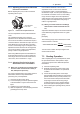
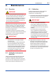
6.6 Power Supply Voltage and
Load Resistance
When conguring the loop, make sure that the
external load resistance is within the range in the
gure below.
(Note) In case of an intrinsically safe transmitter, external load
resistance includes safety barrier resistance.
600
250
0 10.5 16.6 25.2 42
External
load
resistance
R (Ω)
Power supply voltage E (V DC)
F0612.ai
Communication
applicable range
BRAIN and HART
R=
E–10.5
0.0244
Figure 6.12 Relationship between Power Supply
Voltage and External Load Resistance