GENERAL ELECTRIC COMPUTERS GE-200 Series Operating Manual
G E - 2 0 0 SERIES OPERATING MANUAL December Rev.
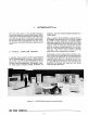
PREFACE This manual has been prepared a s a guide to operating the central processor for the GE-225 Information Processing system. It includes a brief description of the major components of the system, general operating practices, system startup and shutdown, and a detailed description of the controls on the operator's cocsole and ty2ewriter. P a r t I has been revised to include descriptions and illustrations of equipment not included in the e a r l i e r editions of this manual.
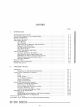
Page INTRODUC TION A Typical Computer Center . . . . . . . . . . . . . . . . . . . . . . . . . . . . . . . . . . . . . The GE-225 Information Processing System . . . . . . . . . . . . . . . . . . . . . . . . Systemconfiguration . . . . . . . . . . . . . . . . . . . . . . . . . . . . . . . . . . . . . . . . . . The Central P r o c e s s o r . . . . . . .. . ........................ ... Input-OutputDevices . . . . . . . . . . . . . . . . . . . . . . . . . . . . . . . . . . . . . . . . . . CardReaders . . . .
Figure IIIIII- 1 2 3 4 5 6 I- 7 I- 8 I- 9 1-10 1-11 1-12 Page The The The The The The ...................... ............. .................................... ............................. ................................ GE -22 5 Information Processing System GE-225 System Using Punched Card Input and Output 6 3 - 2 2 5 System Using Paper Tape Input and Output . . . . . . . . . . . . . . Central P r o c e s s o r 400 Card-Per-Minute Reader High Speed C a r d Reader .......................... .......
Page Figure 11-11 11- 12 IV- 1 IV- 2 Iv- 3 IV- 4 v- 1 .................................... ............................... .................................... ................... ...................................... ......................... ......................................
f. glow green). This places the document handler's electronics in a standby condition. peripherals a r e contained in sections of this manual under headings of the specific peripherals. 4. D e p r e s s the MOTOR ON pushbutton on the control and indicator panel (will glow green). SHUTDOWN PROCEDURES 5. D e p r e s s the ON-LINE, OFF-LINE MODE pushbutton on the control and indicator panel for the desired setting.
b. 3. 4. High speed p r i n t e r : a. D e p r e s s the O F F LINE switch on the controller. b. D e p r e s s the POWER O F F switch on the controller. 11. C a r d punch: a. c. 5. D e p r e s s the MANUAL CYCLE switch until the punch is c l e a r of cards. 6. Typewriter: P u t the power switch under right side to O F F position (white will disappear in viewing window and O F F will appear). 7. 1000 c a r d p e r minute reader: 8. a.
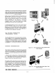
IV. CENTRAL PROCESSOR GENERAL DESCRIPTION The central processor (Figure IV-1) performs the computational (arithmetic), the storage, and the control functions f o r the GE-225 System. The processor is housed in three equipment racks which a r e bolted together. The console indicating and control panel (usually termed the control console) is mounted on the side of the f i r s t rack. Below the panel is the console desk and above i t is the half -length door covering a maintenance control panel.
The second rack contains the majority of the electronic counters, registers, timing circuits, and control logic associated with the processor. The third rack contains the remaining registers, the magnetic core memory and i t s associated timing and control logic, and the logic for the controller selector. Cable Connections All peripherals a r e connected to the central process o r by cables. The typewriter is connected directly by cable to the f i r s t rack of the central processor.
engineers, but t h e r e a r e two i t e m s of concern to the operator, the N r e g i s t e r indicators and the CLEAR N Switch. N Register Indicators. These lights a r e located in the upper right c o r n e r of the maintenance panel and a r e labelled N1, N2, N3, N4, N5, and N6. TL.ey show the contents of the N regi s t e r which is a BCD character representation of the input o r output f o r either the paper tape r e a d e r , p a p e r tape punch, o r the typewriter. CLEAR N Switch.
tempt to select a controller through the controller selector for an input/output operation. The ECHO alarm light can be turned off only by depressing the RESET ALARM switch. The alarm indicates the following conditions: - - - P - - - - 5 CLRQ E:k: PUNCH - 4 3 2 1 - 5 6 PUNCH READY - 7 - 8 9 10 The selected controller is busy (delay not programmed). 2. An erroneous address was programmed, the addressedplug is not installed. CARD CARD READER ECHO ALARM - - - 1 1.
3. Controller is off line. 4. Power is off to controller. 5. Controller is malfunctioning. CARD READER Alarm. This a l a r m is turned on when attempting to execute an RCB, RCD, o r RCF instruction while the c a r d r e a d e r is not in the ready condition. When the CARD READER a l a r m comes on, the PRIORITY a l a r m also comes on and the c a r d r e a d e r and the central p r o c e s s o r halt. The a l a r m s in this combination a r e r e s e t only by depressing the RESET ALARM switch.
the index groap that has been selected by the p r o g r a m (Groups 0 through 3 1). Each group has four r e g i s t e r s , 0 through 3. When a l l lights a r e off, group z e r o is available without special selection. Only index groclp z e r o is standard on the GE-225 System; additional groups a r e optional. Any time a light is on in the index group, the o2erator knows that an index g r m p other than z e r o has been selected. P Counter Lights.
mistake by clearing the A r e g i s t e r with the R.3SE'I: A switch and then starting over. When the computer is in the altomxtic m3de, the o2erator must be v e r y careful nt2t to aczidentally lower the R-ZSET A switch. If he sh9uld lower i t accidentally, branzh cammands wvl~ld n ~ oporate t corre.2tly. The operator would proSably not kn3w of the e r r o r he caused until the p r o g r a m m e r reported back to him that the r u n was confused. Toggle.
START, In the automatic mode of operation, depressing the START pushbutton initiates action. After the operation begins, the program runs automatically and despressing the START switch again has no effect. In the manual mode of operation, depressing the START switch causes the execution of one instruction o r one word time, depending upon the setting of the INST/WORD switch. A 4 I (A to I). This switch i s effective only in the manual mode of operation.
TABLE I. FUNCTIONS OF CONTROLS AND INDICATORS O N CENTRAL PROCESSOR r Group Alarm Indicator Lights Ready Indicator Lights Control o r Indicator Func t lon PRIORITY a l a r m light (red) Indicates: 1. AUTO/MANUAL switch is in NlANUAL position. 2 , P a r i t y alarnl condition. 3 . Central p r o c e s s o r does not have priority. 4. Card punch o r c a r d r e a d e r a l a r m condition. PARITY a l a r m light (red) Indicates: 1.
Group Ready Indicator Lights (Cont. ) Register Display Lights and Switches Control o r Indicator Function CARD READER READY light (green) Indicates when c a r d r e a d e r is in 'ready'status. N REGISTER READY light (green) Indicates N r e g i s t e r is ready to receive input/output information and no illegal o r improperly programmed instruction h a s been given to typewriter o r papertape reader/punch. AIM light (green) Indicates that optional automatic interrupt mode is operative.
Control o r Indicator Group Control Switches Fuilc t ion PWR ON switch Applies DC power to the c e n t r a l p r o c e s s o r , and 400 card/minute reader. PWR O F F switch T u r n s off DC power to the cent r a l p r o c e s s o r , control console, and 400 card/minute r e a d e r . RESET ALARM switch C l e a r s a l a r n l conditions (effec tive only when MANUAL switch is engaged).
v Group Mainteilanc e Panel Control o r Indicator Function N register indicators Shows contents of N register input o r output for the paper tape reader, paper tape punch, or typewriter. CLEAR N switch Clears contents of N register to zero.
SETUP PROCEDURES Setting up the central p r o c e s s o r f o r operation involves only bringing power up and setting control switches. The s i x s t e p s listed below a r e designed to save data in the c o r e m e m o r y of the central processor. If the console was previously shut down by the normal procedure and switches have not been disturbed, s t e p s 2 and 3 require only verification.
3. Toggle the RESET A switch. 4. Load an STA instruction in the A r e g i s t e r (Store A is an octal 0300000), with the m e m o r y a d d r e s s where the data i s to be s t o r e d replacing the 13 righthand bits of the STA instruction. 5. D e p r e s s the A to I switch. 6. Toggle the RESET A switch. 7. Load the octal equivalent of the data to be s t o r e d into the A register. 8. D e p r e s s the START switch. branch instruction modified by index r e g i s t e r 1, 2, o r 3.
a. If a binary c a r d , u s e RCB, octal 250YY01. 3. b. If a decimal card, u s e RCD, octal 250YYOO. 4. Raise the optioil switches corresponding to YY is the starting a d d r e s s where the c a r d is to be read. The handiest a d d r e s s is z e r o ; i f this cannot be used, r e m e m b e r that the a d d r e s s must be a multiple of 128 and l e s s than 2048; that is, multiples of octal 200 and l e s s than octal 4000. 4. D e p r e s s the A to I switch. 5.
Sequencing through Programs It is possible to manually sequence through a prog r a m , step by step, and examine each instruction by reading the instruction register. This i s accomplished with the following steps. (Assume the INSTR switch is engaged) : 1- S e t the AUTO/MANUALswitch to MANUAL, 2. Branch to the starting location of the prog r a m to be examined: a.
the SAVE P switch to p r e s e r v e the contents of the P register. Also, record the contents of the A r e g i s t e r on the log sheet. 3. 4. B. Introduce a SET PST instruction (octal 2506015) into the computer through the control console using the technique described under ' Loading an Instruction Manually. ' Resetting the PARITY Alarm Two methods of resetting a PARITY a l a r m will be described.
a parity a l e r t is detected during a production run, the central p r o c e s s o r halts and all p e r i p h e r a l s halt aft,er conlpleting their l a t e s t instruction. At this time i t is mandatory that the operator consult the operating instructions (run book) before doing anything to the equipment. It will usually be n e c e s s a r y to return the progsarrl to the n e a r e s t r e s t a r t point.
1. Set the AUTO/MANUAL switch to MANUAL. 2. D e p r e s s the LOAD CARD switch to move the f i r s t c a r d , (assuming no a l a r m s were on). 3. D e p r e s s the RESET ALARM switch. 4. D e p r e s s the LOAD CARD switch to read the first c a r d into memory. 5. D e p r e s s the RESET P switch. 6, 7.
TABLE II. CONTROL CONSOLE ERROR CONDITIONS E r r o r Condition PRIORITY a l a r m light (red) c o m e s on Possible Cause Central p r o c e s s o r is in the manual mode Corrective Action When ready to go into automatic mode, p r e s s RESET ALARM and the AUTO portion of the AUTO/MANUAL switch.
E r r o r Condition Possible Cause Corrective Action CARD PUNCH a l a r m light (red) c o m e s on; computer halts. C a r d punch not ready when a WCB, WCF, o r WCD instruction was given Make c a r d punch ready and consult run book for r e s t a r t procedures CARD READER a l a r m light (red) c o m e s on; computer halts.
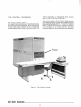
V. CONSOLE TYPEWRITER GENERAL DESCRIPTION . " The console electric typewriter (Figure V-1) is an output device located on the operator's control console desk. Its principal purpose is to permit the computer to communicate with the operator by printing messages under program control. However, it is possible for the typewriter to be used by the program- m e r for more extensive informational output. This would usually happen only in situations when a high speed printer is not available.
Red printout Black printout P r i n t c h a r a c t e r s 0-9, A-Z, minus, period, slash, dollar, and comma Carriage return Space (by operation of the blank key) Tabulation M e s s a g e s a r e typed out automatically, requiring no assistance f r o m the operator. However, a typeout should be immediately observed since the message m a y contain instructions requiring a decision and action on the operator's part. All e r r o r m e s s a g e s a r e printed in red.
ulator settings will be a t 10 and 20 spaces from the left margin. Messages of ageneral nature will originate at the left margin. Messages pertaining to input will be indented to the first tab setting and messages pertaining to output will be indented to the second tab setting. The steps in setting tab stops a r e : (Only two settings a r e described, but the same procedure applies to any number of settings.) a. Move the carriage to the right end of the writing line by tabulating with the TAB KEY. b.
TABLE lrl TYPEWRITER ERROR CONDITIONS E r r o r Condition Corrective Action Possible Cause Keyboard is locked. Typewriter was not manually turned on Turn typewriter on, d e p r e s s CLEAR N hutton on the console inaintenance panel, and r e s t a r t the program. The typewriter is jammed and the N r e g i s t e r ready light on the console is out. The necessary 200 m s delay was not programmed between the TON and the TYP commands D e p r e s s anv alphabetic key.
NUMBER SYSTEMS I NUMBER SYSTEMS IN GENERAL following i s an example of a binary number: To l e a r n and understand new nunlber s y s t e m s , i t is necessary to analyze principles which a r e true of all number systems: A number is expressed a s the sum of terms. The number 26 i s the decimal equivalent of binary 11010, so it i s seen that the expansion of a binary number by powers i s a simple method of converting from binary to decimal.
D. Octal Representation of Binary Numbers Because the base "8" of the octal number system is a power of 2--the base of the binary system -- three binary numbers may be read as one octal number. This grouping of binary numbers into octal representation is e a s i e r to read than straight binary. To illustrate: 11. ARITHMETIC COMPUTATIONS IN BINARI AND OCTAL A. Binary Arithmetic 1.
More Examples: Division: 45 101101 -25 - 11001 Difference: 20 10100 Difference: 44 34 10 354 -170 184 101100010 - 10101010 10111000 101100 -100010 001010 Division by the computer i s in binary, and is a s e r i e s of repeated subtractions. A second method of subtracting, called the 2 ' s cornplenlent method, i s particularly good to understand, for i t is the way the computer handles subtraction in i t s internal operation.
3. Multiplication: B. Multiplication in octal can best be done by using the table below. Octal X 1 2 3 4 I 5 6 7 Binarv to Decimal The expansion method used in paragraph IB of this Annex converts a binary number to i t s decimal equivalent. This method r a i s e s the base 2 to the proper power and then multiplies by 0 o r 1. 10 1 Given the binary number 100101, find i t s decimal equivalent: C. 4.
F. Binary to Octal Binary digits can easily be converted to octal by dividing the digits into groups of three, beginning the grouping at the right with the least significant digit a s follows: which is 1654 in octal.
T a b l e of Powers of 2
Octal-Decimal Integer Conversion Table Octal 10000 20000 30000 40000 50000 60000 70000 becirnal 4096 8192 12288 16384 20480 24576 28672 Octal 1 0 0 0 0 to 0 3 7 7 Decimal ( 0 0 0 0 to 0 2 5 5 Octal 0 1 2 3 4 5 6 7 0000 0010 0020 0030 0040 0050 0060 0070 0000 0008 0016 0024 0032 0040 0048 0056 0001 0009 0017 0025 0033 0041 0049 0057 0002 0010 0018 0026 0034 0042 0050 0058 0003 0011 0019 0027 0035 0043 0051 0059 0004 0012 0020 0028 0036 0044 0052 0060 0005 0013 0021 0029 0037 00
Octal-Decimal Integer Conversion T a b l e Octal 10000 20000 30000 40000 50000 60000 70000 Decimal 4096 8192 12288 16384 20480 24576 28672 Octal 0 1 2 3 4 5 6 7 Octal 0 1 2 3 4 5 6 7 2000 2010 2020 2030 2040 2050 2060 2070 1024 1032 1040 1048 1056 1064 1072 1080 1025 1033 1041 1049 1057 1065 1073 1081 1026 1034 1042 1050 1058 1066 1074 1082 1027 1035 1043 1051 1059 1067 1075 1083 1028 1036 1044 1052 1060 1068 1076 1084 1029 1037 1045 1053 1061 1069 1077 1085 1030 10
Octal-Decimal Integer ConversionTa b l e Octal 10000 20000 30000 40000 50000 60000 70000 Decimal 4096 8192 12288 16384 20480 24576 28672 E Octal 5 0 0 0 to 5 3 7 7 Decimal 2 5 6 0 to 2815 Octal 0 1 2 3 4 5 6 7 Octal 0 1 2 3 4 5 6 7 4000 4010 4020 4030 4040 4050 4060 4070 2048 2056 2064 2072 2080 2088 2096 2104 2049 2057 2065 2073 2081 2089 2097 2105 2050 2058 2066 2074 2082 2090 2098 2106 2051 2059 2067 2075 2083 2091 2099 2107 2052 2060 2068 2076 2084 2092 2100 21
Octal-Decimal Integer Conversion Table Octal 10000 20000 30000 40000 50000 60000 70000 Decimal 4096 8192 12288 16384 20480 24576 28672 Octal 0 1 2 3 4 5 6 7 Octal 0 1 2 3 4 5 6 7 6000 6010 6020 6030 6040 6050 6060 6070 3072 3080 3088 3096 3104 3112 3120 3128 3073 3081 3089 3097 3105 3113 3121 3129 3074 3082 3090 3098 3106 3114 3122 3130 3075 3083 3091 3099 3107 3115 3123 3131 3076 3084 3092 3100 3108 3116 3124 3132 3077 3085 3093 3101 3109 3117 3125 3133 3078 3086 30
Octal-Decimal Fraction Conversion Table OCTAL DECIMAL OCTAL DECIMAL I OCTAL DECIMAL I OCTAL DECIMAL
Octal-Decimal Fracctioh Conversion T a b l e OCTAL DECIMAL OCTAL DECIMAL OCTAL DECIMAL OCTAL DECIMAL .OOOOOO .000001 .000002 .000003 .000004 .000005 .000006 .000007 .OOOOOO .000003 .000007 .000011 .000015 .000019 .000022 .000026 .000100 .000101 .000102 .000103 .000104 .000105 .000106 .000107 .000244 .000247 .000251 .000255 .000259 .000263 .000267 .000270 .000200 .000201 .000202 .000203 .000204 .000205 .000206 .000207 .000488 .000492 ,000495 ,000499 .000503 .000507 .000511 .000514 .000300 .
Octal-Decimal Fraction Conversion T a b l e OCTAL DECIMAL OCTAL DECIMAL OCTAL DECIMAL OCTAL DECIMAL .001708 .001712 .001716 .001720 .001724 .001728 .001731 .
REPRESENTATION OF GE-225 CHARACTERS I HIGH PSPEED RMTER SYhIUOLS 0 0 I Space / 1 COXSOLE TYPEWRITER CHARACTER OR ACTION I 0 1 P A P E R TAPE CHARACTER ( a CIIAKXEL) Suace I-IOLLERITH CODE (PC'XCH LU ROWS) 1 MEMORY BCD (OCTAL)** 00 (1 1 MAGNETIC TAPE (OCTAL) 12 I Blank / 11-5-b -- --- P r i n t Red -.
LISTING OF SEPARATE SUBSYSTEM MANUALS The peripheral subsystems formerly described in Chapters VI through XVIII of the GE-225 System Operating Manual (CPB-247) a r e now covered in separate manuals. These manuals contain complete programming and operating information for these subsystems. Manual Title and Publication No. Peripheral Subsystem 400-cpm Card Reader 1000-cpm Card Reader 1 Punched Card Subsystems Reference Manual (CPB-302) 100-cpm Card Punch 300-cpm Card Punch J 15- and 15/41-KC.
I I I I I DOCUMENT REVIEW SHEET TITLE: CPB #: .GE-200 S e r i e s O p e r a t i n g Manual 247C FROM' Name: Position: Address: Comments c o n c e r n i n g t h i s p u b l i c a t i o n are s o l i c i t e d f o r u s e i n i m p r o v i n g f u t u r e e d i t i o n s . P l e a s e p r o v i d e any recommended a d d i t i o n s , d e l e t i o n s , c o r r e c t i o n s , o r o t h e r i n f o r m a t i o n you deem n e c e s s a r y f o r i m p r o v i n g t h i s m a n u a l .
STAPLE FOLD L FIRST CLASS PERMIT, NO.
LKHO U.S.A.