Application for Drive Technology MICROMASTER 4 Application Description MICROMASTER 420 / 440 DC link coupling between several frequency inverters
Warranty, Liability and Support MICROMASTER 420 / 440 – DC link coupling between several Frequency inverters 1 Warranty, Liability and Support We do not accept any liability for the information contained in this document. Copyright © Siemens AG 2005 All rights reserved Any claims against us – based on whatever legal reason – resulting form the use of the examples, information, programs, engineering and performance data etc., described in this document shall be excluded.
Definitions and Warnings MICROMASTER 420 / 440 – DC link coupling between several Frequency inverters 2 Definitions and Warnings 2.1 Qualified personnel In the sense of this documentation, qualified personnel are those who are knowledgeable and qualified to install, mount, commission, operate and service/maintain the MICROMASTER 4 products to be used. He or she must have the appropriate qualifications to carry-out these activities.
Definitions and Warnings MICROMASTER 420 / 440 – DC link coupling between several Frequency inverters 2.4 Information regarding trademarks MICROMASTER® is a Siemens registered trademark MASTERDRIVES® is a Siemens registered trademark 2.5 Revisions/author Date/change Author 1.1 14.10.03 / First edition in English language Haßold 1.3 20.09.04 / Changes in Section “ Definitions and Warnings”; additional note regarding the connection of the single phase inverters to the mains in Section 3.1.
Introduction MICROMASTER 420 / 440 – DC link coupling between several Frequency inverters 3 Introduction The DC links of MICROMASTER 420 and MICROMASTER 440 frequency inverters can be coupled with one another using the DC link coupling. In this case, the frequency inverters exchange energy with one another through the common DC link.
Introduction MICROMASTER 420 / 440 – DC link coupling between several Frequency inverters 4 Operation with only one supply frequency inverter With this configuration, only one frequency inverter is connected to the line supply and one or several frequency inverters is/are connected to the supply inverter through the DC link. This then provides the energy for the frequency inverters coupled at the DC link. 3-ph. 200-240V AC 50/60Hz 3-ph.
Introduction MICROMASTER 420 / 440 – DC link coupling between several Frequency inverters 4.1 Frequency inverter versions and power ratings which can be coupled MICROMASTER 420 and MICROMASTER 440 frequency inverters can be operated together as well as mixed in a DC link group. In mixed operation, both frequency inverter types can be used as the supply inverter connected to the line supply.
Operation with only one supply frequency inverter MICROMASTER 420 / 440 – DC link coupling between several Frequency inverters 4.2 Options required at the line supply input of the supply inverter The fuses, circuit-breaker and a possible externally mounted EMC filter should be used, according to Catalog DA51.2, at the line side of the supply inverter as for frequency inverters operated in the standalone mode.
Operation with only one supply frequency inverter MICROMASTER 420 / 440 – DC link coupling between several Frequency inverters In order to simplify the equation, the following assumptions are made: cosφMotor = 0.86 VA / Vmax = 1 (operation at the max. frequency inverter voltage) ηINV = 0.97 This means the following: IDC = 1.20 • IA At the rated operating point with the rated output current IAN: IDCN = 1.
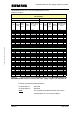
Operation with only one supply frequency inverter MICROMASTER 420 / 440 – DC link coupling between several Frequency inverters Rated currents and recommended DC link fuses of the MICROMASTER 420/440 inverters, versions without/with filter CT (Constant Torque) Power Rated input current Rated output current Rated DC link current kW A A A VT (Variable Torque) Required DC link fuses 2x per converter are required Order No.
Operation with only one supply frequency inverter MICROMASTER 420 / 440 – DC link coupling between several Frequency inverters Rated currents and recommended DC link fuses of the MICROMASTER 420/440 drive converters, versions without/with filter CT (Constant Torque) Power Rated input current Rated output current Rated DC link current kW A A A VT (Variable Torque) Required DC link fuses 2x per converter are required Order No.
Operation with only one supply frequency inverter MICROMASTER 420 / 440 – DC link coupling between several Frequency inverters 4.3.1 Connecting the DC link coupling at the frequency inverter The DC link couplings are connected at terminals DC + und DC – of the frequency inverter. Terminals DC + are connected with DC + and DC – with DC – of the frequency inverter.
Operation with only one supply frequency inverter MICROMASTER 420 / 440 – DC link coupling between several Frequency inverters gland plate can be used. For the DC link fuses, the shield should be connected to the mounting plate. Note: When implementing the DC link couplings, it is also important that the plant/system and country-specific regulations are carefully observed. 4.3.
Operation with only one supply frequency inverter MICROMASTER 420 / 440 – DC link coupling between several Frequency inverters Note: When fusing/protecting the frequency inverters and DC link couplings, it is also important that the plant/system and country-specific regulations are carefully observed. Example 1: L1 3-ph.
Operation with only one supply frequency inverter MICROMASTER 420 / 440 – DC link coupling between several Frequency inverters Copyright © Siemens AG 2005 All rights reserved In this particular case, the supply inverter (75kW) is fused, on the line side with the fuses (200A) specified in the Operating Instructions. The frequency inverters (11kW and 7.5kW) connected to its DC link must be separately fused as they cannot be protected by the 200A line fuses of the supply inverter.
Operation with only one supply frequency inverter MICROMASTER 420 / 440 – DC link coupling between several Frequency inverters Example 2: 3-ph. 380-480V AC 50/60Hz L1 L2 L3 PE Line fuses 3 x 10A Line contactor Line reactor PE Inverter PE MM440 MM440 MM420 1,5kW 0,55kW 0,55kW PE Copyright © Siemens AG 2005 All rights reserved PE PE PE M 3~ M 3~ M 3~ Motor Motor Motor Fig. 2-3: DC link coupling of a 1.5kW MM440 frequency inverter with an 0.55kW MM440 and a 0.
Operation with only one supply frequency inverter MICROMASTER 420 / 440 – DC link coupling between several Frequency inverters 4.3.4 Maximum DC link - cable lengths The total length of the DC link couplings as a sum, starting from the supply inverter is 5m. 4.4 Braking operation of the DC link group For the DC link coupling, energy is exchanged between the frequency inverters through a common DC link.
Operation with only one supply frequency inverter MICROMASTER 420 / 440 – DC link coupling between several Frequency inverters The DC braking – function in the inverter can be used as an alternative to regenerative braking using the integrated braking chopper. This can be activated for every connected frequency inverter. It is not permissible that the compound braking is activated.
Operation with only one supply frequency inverter MICROMASTER 420 / 440 – DC link coupling between several Frequency inverters 4.8 Operation of the fans in the frequency inverters In order that the supply inverter is not thermally overloaded, when one of the connected frequency inverters receives an ON command then the supply inverter must also receive an ON command. This therefore guarantees that its fan is operational and the cooling is adequate.
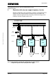
Operation with only one supply frequency inverter MICROMASTER 420 / 440 – DC link coupling between several Frequency inverters 5 Operation with up to three supply inverters If several drives predominantly operate in the motoring mode in a DC link group, then one supply inverter is no longer sufficient. In this case up to three frequency inverters can be connected to the line supply and coupled through the DC link. Additional frequency inverters can be connected to this DC link group and supplied. 3-ph.
Operation with up to three supply inverters MICROMASTER 420 / 440 – DC link coupling between several Frequency inverters 5.1 Frequency inverter versions and power ratings which can be coupled MICROMASTER 420 and MICROMASTER 440 frequency inverters can be operated both with one another as well as mixed in a DC link group. In mixed operation, both frequency inverter types can be used as the supply frequency inverter connected to the line supply.
Operation with up to three supply inverters MICROMASTER 420 / 440 – DC link coupling between several Frequency inverters Copyright © Siemens AG 2005 All rights reserved the individual frequency inverters. This can therefore avoid overloading the rectifier integrated in the frequency inverter. The frequency inverters which are not used to supply the DC link group do not have to be overdimensioned and can be dimensioned corresponding to the connected motor load.
Operation with up to three supply inverters MICROMASTER 420 / 440 – DC link coupling between several Frequency inverters The required supply power of 75kW can, for example, be split-up as follows: Motor power of the supply inverters: Required power of the supply inverters: 11kW => 15kW (overdimensioned by a factor of 1.35) 15kW => 30kW 1) 22kW => 30kW (overdimensioned by a factor of 1.35) 1) Overdimensioned by more than a factor of 1.
Operation with up to three supply inverters MICROMASTER 420 / 440 – DC link coupling between several Frequency inverters Note: Under certain circumstances it is no longer guaranteed that the EMC limit value classes will be able to be fully maintained. It is therefore absolutely necessary that the EMC Guidelines, specified in the frequency inverter Operating Instructions are carefully maintained. 5.
Operation with up to three supply inverters MICROMASTER 420 / 440 – DC link coupling between several Frequency inverters The rated currents and the required DC link fuses of the MICROMASTER420 and MICROMASTER440 frequency inverters are listed in the following Tables 3-1 and 3-2.
Operation with up to three supply inverters MICROMASTER 420 / 440 – DC link coupling between several Frequency inverters Note: The cylindrical fuse disconnectors may only be switched when in a no-current condition.
Operation with up to three supply inverters MICROMASTER 420 / 440 – DC link coupling between several Frequency inverters 5.3.1 Connecting the DC link coupling at the frequency inverter The DC link connections are connected at the frequency inverter at terminals DC + und DC – . Terminals DC + are connected with DC + and DC – with DC – of the frequency inverter.
Operation with up to three supply inverters MICROMASTER 420 / 440 – DC link coupling between several Frequency inverters The DC link couplings must be appropriately implemented for the voltages which occur. The required voltage strength is: o 450V DC for a line supply voltage of 1/3-ph. 200-240V AC o 900V DC for a line supply voltage of 3-ph. 380-480V AC Copyright © Siemens AG 2005 All rights reserved A shielded cable must be used for the DC link coupling in order to reduce EMC noise/disturbances.
Operation with up to three supply inverters MICROMASTER 420 / 440 – DC link coupling between several Frequency inverters In this particular case, the five frequency inverters connected to the DC link are fused with the DC link fuses specified in Table 3-2. The line fuses of the supply inverters are selected according to the Operating Instructions. The cable cross-sections to couple the DC link terminals of the inverters to the DC link fuses are determined corresponding to the downstream DC link fuses.
Operation with up to three supply inverters MICROMASTER 420 / 440 – DC link coupling between several Frequency inverters Copyright © Siemens AG 2005 All rights reserved Note: o The integrated braking chopper is only active if the frequency inverter had received an ON command and is actually operational. When the appropriate frequency inverter is powered-down, then energy cannot be pulsed in the braking resistor. o The braking resistors, which are used in the Catalog DA51.
Operation with up to three supply inverters MICROMASTER 420 / 440 – DC link coupling between several Frequency inverters 5.6 DC link voltage controller operation For a DC link coupling, the VDCmax controller, integrated in the MICROMASTER 420 and MICROMASTER 440 frequency inverters may not be used. This controller is activated in the factory setting which means that it must be disabled by setting parameter P1240 to 0.
Operation with up to three supply inverters MICROMASTER 420 / 440 – DC link coupling between several Frequency inverters 5.9 Risk for the connected frequency inverters in the case of a DC link short-circuit When a short-circuit or ground fault occurs in the DC link (in the DC link coupling or within a frequency inverter), there is a risk that all of the frequency inverters, connected to the DC link, will be destroyed.