
Operating instructions
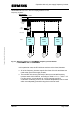

Operation with only one supply frequency inverter
MICROMASTER 420 / 440 – DC link coupling between several
Frequency inverters
The DC braking – function in the inverter can be used as an alternative to
regenerative braking using the integrated braking chopper. This can be
activated for every connected frequency inverter. It is not permissible that
the compound braking is activated. The reason for this is that this can
automatically be switched-in, as a function of the DC link voltage and result
in undesirable braking operations.
4.5 Max. motor cable lengths
The max. motor cable length of all of the frequency inverters connected in
the DC link group may not exceed, in total, 200m (shielded) and 300m
(non-shielded). Otherwise, their rectifier and the EMC filters could be
overloaded due to the discharge (leakage currents) which flow with respect
to PE and which flow back through the supply inverter. An output reactor
should be used for the individual frequency inverters for motor cable lengths
exceeding 50m (shielded) and 100m (non-shielded) as specified in Catalog
DA51.2.
4.6 DC link voltage controller operation
For a DC link coupling, the V
DCmax
controller, integrated in the
MICROMASTER 420 and MICROMASTER 440 frequency inverters may
not be used. This controller is activated in the factory setting which means
that it must be disabled by setting parameter P1240 to 0.
Copyright © Siemens AG 2005 All rights reserved
However, the kinetic buffering in the MICROMASTER 440 frequency
inverter can be used to buffer the DC link during brief power failures. In this
case, parameter P1240 must be set to 2.
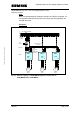
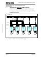
4.7 Accommodating the frequency inverters connected to the DC
link in a cabinet
The frequency inverters, coupled through the DC link, must be located next
to one another in the electric cabinet in the same sequence as their rated
powers. Generally, the supply inverter is the inverter with the highest power
rating in the DC link group. The frequency inverters must be arranged
directly next to one another in order to keep the DC link couplings as short
as possible.
A&D SD Page 18/32