Weighing Indicator for Check Weighing Scales 1WMPD4002313
This Manual and Marks All safety messages are identified by the following, “WARNING” or “CAUTION”, of ANSI Z535.4 (American National Standard Institute: Product Safety Signs and Labels). The meanings are as follows: WARNING A potentially hazardous situation which, if not avoided, could result in death or serious injury. CAUTION A potentially hazardous situation which, if not avoided, may result in minor or moderate injury. This is a hazard alert mark.
Contents 1. COMPLIANCE ................................................................................................. 2 2. INTRODUCTION .............................................................................................. 3 3. UNPACKING .................................................................................................... 4 4. INSTALLATION and PRECAUTIONS ............................................................. 5 4-1. Precautions for Installing the Indicator ..................
1. COMPLIANCE Compliance with FCC rules Please note that this equipment generates, uses and can radiate radio frequency energy. This equipment has been tested and has been found to comply with the limits of a Class A computing device pursuant to Subpart J of Part 15 of FCC rules. These rules are designed to provide reasonable protection against interference when equipment is operated in a commercial environment.
2. INTRODUCTION This manual describes how this product works and how to get the most out of it in terms of performance. The FS-D weighing indicator is used to build high performance check weighing scales. It has similar specifications and functions as an indicator of the FS-i series. Please refer to the instruction manual for the FS-i supplied with the FS-D. The FS-D indicator has the following features.
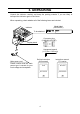
3. UNPACKING Unpack the indicator carefully and keep the packing material if you are likely to transport the indicator again in the future. When unpacking, check whether all of the following items are included: Model label (1083014607) Indicator To be attached. Connector plug (1JMNJW-165-PM7) Display stand Hexagonal wrench (1.27 mm / 0.05 inch) Main power cord Set Up Instruction (this manual) Please confirm that the main power type is correct for your local voltage and receptacle.
4. INSTALLATION and PRECAUTIONS 4-1. Precautions for Installing the Indicator Ground the indicator so that the user will not be subjected an electric shock. Do not handle the main power cord with wet hands. The AC plug is not water-resistant. Install it in an area where it does not get wet. Do not install the indicator where there is flammable or corrosive gas present. Do not install the indicator under water. Do not pull, fold or arrange cables forcibly.
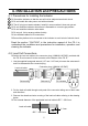
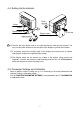
4. Solder the wires to the pin contacts of the connector. A 5 m or less load cell cable is recommended as the FS-D uses a 4 wire system (no remote sensing). Load cell cable Load cell connector SIGEXC+ SIG+ EXC- Load cell Shield 5. Reassemble the connector plug and tighten the setscrew A. 6. Move the load cell cable back and forth and around, and tighten each parts again. Finally, tighten the setscrew B. Setscrew B Setscrew A 7.
4-4. Setting Up the Indicator Earth terminal Clamp Clamp Display stand Earth terminal To the wall Display stand (Wall-mounting bracket) Connect the main power cord to an outlet that has an earth ground terminal. You may use the earth terminal on the rear side of the display to ground the indicator. If necessary, adjust the viewing angle of the display by loosening the 2 clamps, changing the angle and re-tightening the clamps.
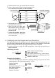
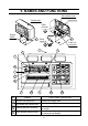
5. NAMES AND FUNCTIONS CAL switch cover Cable hook Display pod Earth terminal Display stand Earth terminal Load cell connector 5 2 1 6 8 7 9 10 4 No. 3 4 11 NAMES 12 FUNCTIONS / OPERATION 1 WEIGHT DATA DISPLAY Indicates the weight data. 2 WEIGHING UNIT INDICATOR Indicates the weighing unit in use. 3 ANALOG WEIGHT DISPLAY 4 OVER RANGE INDICATORS Indicates zero to full scale or comparison limits and results. Turns ON when the weight is outside the range of the analog sweep display.
No. NAMES FUNCTIONS / OPERATION 5 COMPARISON INDICATORS Indicates the results of the weight comparison LO (RED), OK (GREEN) and HI (YELLOW). 6 STABLE ANNUNCIATOR Turns ON when the weight reading is STABLE. 7 ZERO ANNUNCIATOR 8 NET ANNUNCIATOR 9 PT ANNUNCIATOR 10 PRINT ANNUNCIATOR 11 PRECAUTION AGAINST LOW BATTERY 12 ON/OFF Key ZERO / ± Key TARE Key PT Key SAMPLE / 9 Key KEY / 8 Key RECALL / 7 Key HI / 6 Key LO / 5 Key STORE / 4 Key DISP.
6. FUNCTION PARAMETER SETTINGS To design a platform scale, set the capacity, weighing unit and other functions according to the specifications of the scale. Normally, end users do not have to set these function parameters and these setting can be sealed together with the calibration switch. Parameter -C01-00 Function number 6-1. The procedure for setting parameters Do not set “C01-1”. Once set, the indicator cannot get into the parameter setting procedure again.
6-2.
7. CALIBRATION This function adjusts the scale (indicator) for accurate weighing. Calibration must be done when the FS-D is initially connected to a load cell (base unit). Calibration may also be required according the changes in the environment. CAL switch cover When the scale (indicator) has been moved. When the ambient environment has significantly changed. For regular calibration. Loose the lock screws on the rear side of the display pod, and remove the (CAL) switch cover.
If you need ZERO calibration but do not need SPAN calibration, turn the power off to exit from the calibration procedure. 7. To calibrate with a different weight, change the displayed value using the 10-key pad. If you enter the wrong number, press the C key. The value returns to the capacity and enter the number again. -00020.00 8. Place a calibration weight on the platform with the same value as displayed, and wait until the STABLE indicator turns on. 9. Press the PRINT/ENT key.
8. AUTO-TARE FUNCTION The FS-D has an auto-tare function to be used with the comparator function enabled. If the weight value is within the OK range and stable for a preset time, then the indicator will automatically tare the weight and show zero. The Function “f22” designates the timing to tare automatically. See “9. ADDITIONAL INFORMATION” about the added F-Function settings related to the auto-tare function. To use the auto-tare function, set the function settings below.
9. ADDITIONAL INFORMATION This section describes the additional functions and corrections to the instruction manual of FS-i series (WM+PD4001332 and 1WMPD4001368) which are common to the FS-D. 9-1. F-Function list The following function settings are added (“11-2. Function list” in WM+PD4001332).
The frame ground and the shield are connected internally and there is no difference between them in use. Data format Example of data Out of range “kg” (+) O L , + 9 9 9 9 9 9 9 9 _ k g CR LF Out of range “kg” (+) O L , + 9 9 9 9 . 9 9 9 _ k g CR LF The position of decimal point is different according to the model and/or “f02”. Example for the weighing unit “lb-oz” (added) Weighing data “lb-oz” (+) S T , + 0 0 1 L 0 1 .
Command H I , + 0 0 1 0 0 CR LF Assume 2 decimal place number. Reply H I , + 0 0 1 0 0 CR LF 1.00% will be set as LO limit %. Command L O , + 0 0 1 0 0 CR LF Assume 2 decimal place number. Reply L O , + 0 0 1 0 0 CR LF 1.00% will be set as LO limit %. Store the comparator limits into the specified memory number. (No reply for f20-1.) Reply H I , 0 1 , + 0 0 1 2 0 0 , + 0 0 0 9 0 0 CR LF Reply M L , 0 1 , + 0 0 1 2 0 0 , + 0 0 0 9 0 0 CR LF 9-3.
10. ERROR MESSAGES Overload error ----e--- Warning to indicate that an object beyond the weighing capacity has been placed on the weighing pan. Remove the object from the weighing pan. Power-on error -------- Warning to indicate that an object beyond the power-on zero range (50% of the weighing capacity or 10%) is placed on the weighing platform. Remove the object from the weighing pan. Pressing the PRINT/ENT key, the indicator will show the weight value without zeroing the indicator.
11. SPECIFICATIONS 11-1. Capacity and minimum display C02- setting Capacity kg Min. display Capacity g Min. display Capacity lb Min. display Capacity oz lboz Min. display Capacity Min. display 0* 1 6 15 0.002* 0.005 0.001 0.002 0.0005 0.001 6000 15000 2* 5 1 2 0.5 1 15 35 0.005* 0.01 0.002 0.005 0.001 0.002 240 560 0.1* 0.2 0.05 0.1 0.02 0.05 15 35 0.1 0.1 2 30 0.01 0.005 0.002 30000 10 5 2 70 0.02 0.01 0.005 1120 0.5 0.2 0.1 70 0.1 *: Factory setting 3 60 0.02 0.01 0.005 4 150 0.05 0.02 0.
11-3. Options OP-02 (HC-02i) OP-03 (FS-03i) OP-04 (FS-04i) SLA Battery (Yuasa Battery NP4-6 recommended.) RS-232C + Comparator Relay Output (See note.) RS-422/485 + Comparator Relay Output (See note.) Note OP-03 and OP-04 cannot coexist. 11-4.
3-23-14 Higashi-Ikebukuro, Toshima-ku, Tokyo 170-0013 JAPAN Telephone: [81] (3) 5391-6132 Fax: [81] (3) 5391-6148 A&D ENGINEERING, INC. 1756 Automation Parkway, San Jose, California 95131 U.S.A.