
Manual
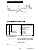


Connection of Control I/O
+v
Input
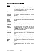
□ This is the interface circuit of the Control I/O .
□ Please use an optical isolator or relay.
□ The extension, or driving capacity of these relays is 24V 50mA DC
maximum.
□ The width of these inputs are at least 100msec.
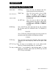
Control I/O Connection Table
Pin No.
Description
Pin No.
Description
A 1
1 ■—1
B 1
Grand total printing command input
2
2 2
Delete command input
3 4
3
Cumulative total delete command input
4 8
Code input (BCD)
4
Input for disable printing time
5
10 5
Busy output
6 20 6
Printing announcement
7
40 7
N.C.
8 80 “ 8
Output common
9 Printing command input
9
For internal use
10
Paper feed command input 10
Input common
11
Addition command input
11
Input common
12
Subtotal printing command input
12
F.G.
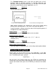
The Pins to change the Control I/O specifications are located on the rear
panel. See drawing below:
12
1
/
DODDODDOQDDD
D D D D D D D D D a D Q
\
A
B
Viewed from the rear panel
The inputs are operated by short-
circuits.The input is a pulse that has a coded
input. These pulse widths are 100 msec, or
longer.
The output is operated by the output
transistor turnnig ON.
/h Note The data will only print when the "Input for disable printing time"
Pin # B-4 is shorted.
Page 10
owners-AD-8118A-v.3.a