
Manual


Description of Panels
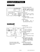
Front Panel
@
© Cover for setting section
Remove this cover and use
the DIP switches to set,
otherwise keep it attached to
prevent dust from getting
inside.
@ Printer cover
Remove this cover to change
printing paper and/or ink
ribbon,
<D POWER indicator
This lights up when the power
is on.
® Operation keys
For operation, refer to
"Operating the Switch Keys," .
Rear Panel
© ®
(D ©
Connector for power cable
Refer to "Connection of Power
Supply/Ground," .
© POWER switch
Turn OFF when not using.
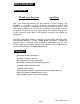
© Fuse
0.5A 100V to 120V{blow)
0.3A 200V to 240V(blow)
@ Standard serial input
connector
Input of RS-232C or current
loop for data.
Refer to "Connection of Serial
Input,".
® Select switch for input mode
This switch is used to select
RS-232C or current loop for
serial inputs. Refer to "Serial
Inputs,".
® Connector for control I/O
This is the I/O area that
controls the printer. Refer to
"Connection of Control I/O,".
Page 6
owners-AD-8118A-V.3.3