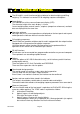
ふ Multi Function Weighing Indicator WM : PD4000243A This is a hazard alert mark.
This mark informs you about the operation of the product. Note This manual is subject to change without notice at any time to improve the product. No part of this manual may be photocopied, reproduced, or translated into another language without the prior written consent of the A&D Company. Product specifications are subject to change without any obligation on the part of the manufacture.
Contents 1. Compliance........................................................................................ 4 1.1.1. Compliance with FCC rules ....................................................... 4 1.1.2. Compliance with European Directives....................................... 4 2. Outline and Features ......................................................................... 5 2.1. Precaution ..................................................................................... 6 2.2.
6.3. 6.3.1. 6.3.2. System Design of a Hopper Scale............................................... 34 Operation and I/O Design........................................................ 34 Design Example ...................................................................... 34 7. Weighing Mode................................................................................ 35 7.1.1. Contents of the Batch Weighing Mode .................................... 35 7.2. Batch Weighing Mode ...........................
8.3. 8.3.1. 8.3.2. 8.3.3. 8.4. 8.5. 8.6. 8.7. 8.8. 8.9. 9. Built-in Current Loop Output ........................................................ 84 Connection .............................................................................. 84 Communication Modes............................................................ 84 Data Format ............................................................................ 85 BCD Output of Option OP-01 ......................................................
1. Compliance 1.1.1. Compliance with FCC rules Please note that this equipment generates, uses and can radiate radio frequency energy. This equipment has been tested and has been found to comply with the limits of a Class A computing device pursuant to Subpart J of Part 15 of FCC rules. These rules are designed to provide reasonable protection against interference when this equipment is operated in a commercial environment.
2. Outline and Features Features The AD-4402 is a multi-function weighing indicator for batch weighing and filling weighing. This indicator has control I/O for weighing sequence and options. Large display This indicator has a blue vacuum fluorescent display (VFD). The character height of the main display is 18 mm. Current weighing data, material names, setpoints (comparison references) and total data are displayed at the same time.
2.1. Precaution Before use, confirm the following articles for safe operation. Grounding the indicator Ground the indicator. The earth terminal is on the rear panel. Separate this earth ground line from others, like ground line of a motor, inverter or a power source. Unless the indicator is grounded, it may cause the operator to receive an electric shock, cause operation error or catch fire Use adequate power cord Confirm the AC voltage and current of the power cord.
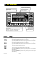
2.2. Front Panel Graphic status indicator Main display Weighing data is displayed. Status indicator Unit indicator Sub-display Materials, Total data, parameters and operation guidance are displayed. 2.2.1. Standby indicator Keys Pressing this key, the key works as the F1 key. Pressing the SHIFT key and this key, the key works as the F3 key. Pressing this key, the key works as the F2 key. Pressing the SHIFT key and this key, the key works as the F4 key. The key to select a function of a key.
The key to move the cursor or scroll the function number. Press and hold the SHIFT key and press the key to decrease the code number. The key to select alphabetical keys, upper keys, lower keys or numerical keys. Alphanumeric keys. The escape key. Pressing and holding the key more than three seconds in normal weighing mode, the display is turned off (standby mode). The ESC key is used to undo the last key action and to return to the last mode. The ENTER key for parameter settings.
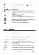
TARE ENT Tare entered. With the tare value stored, this sign is illuminated. HOLD With the main display held, this sign is illuminated. CZ Center of zero. When the gross weight is in the center of the zero point, this sign is illuminated. ZR.ERR Zero error. Error message for zeroing the gross data of the main display. SQ.ERR The sequence error sign. Indicates a weighing sequence error. ALARM 1 An error sign for over load or emergency stop mode. ALARM 2 A fatal error sign.
2.3. Rear Panel Loadcell terminal. Eight 350Ω loadcells can be connected in parallel. Built-in RS-485 terminal. The possibility: to read weighing data, write parameters, connect 32 units of the indicator using with the multi-drop connection. Main power switch Power cord terminal AC85V ~ 250V Control I/O to connect to external control units. 11 input terminals, 11 output terminals, An input common terminal An output common terminal Option slot to connect maximum three options.
3. Installation Caution Remove the power cord before installing the indicator and an option. Turn off peripheral devices before installing it. Insert the options before installing the indicator. 3.1. Mounting Indicator The indicator can be mounted on a panel using the slide rail. If the accessory packing rubber is used, the front panel is equivalent to IP-65 of IEC 529.
3.2. Connecting Loadcell Loadcell Cable Caution Do not share the loadcell cable with noise-generating devices or power lines, beacuse the loadcell signal is very sensitive. We recommend that you use a 6 wire shielded cable to prevent loss of weighing precision. If the loadcell cable length is shorter than 5 m, you may use a 4 wire shielded cable with terminals 1 & 2 shorted (EXC+ & SEN+ shorted) and terminals 3 & 4 shorted (EXC- & SEN- shorted).
3.2.1. Verifying Loadcell Output and Input Sensitivity The input sensitivity of the indicator is 0.3µV/division or more. Adapt to the following inequality, when you design a weighing instrument using the indicator and loadcell(s). Caution A change in input voltage sensitivity is equivalent to a one division change of the display. Select as large an input voltage sensitivity voltage as possible so that the weighing interval becomes stable. Consider the leverage if a lever is used.
3.3. Wiring Power Cord Caution Gorund the indicator using terminal E to avoid receiving an electric shock or an error due to discharge of static electricity. Do not share the ground wire with an electrical device that generates noise. Do not use an unstable power source. Do not share the power cord with a moter system (a noise-generating device) to avoid operation error. The power source can be from AC 85V to AC 250V with 50 Hz or 60 Hz.
3.4. Installing Options Caution Remove the power cord before the operation to install an option. Do not install the same options. Do not touch the internal parts within ten seconds after removing the power cord because you may receive an electric shock. Do not forget to tighten the screws. If a screw is not tightened, it may cause a short circuit or an error due to noise. Three option boards can be installed in the slots. Initialize the RAM data in accordance with section 9.4. Initializing Parameters.
4. Basic Operation 4.1. Key Operation Exam Examples ples This section describes the way of key operation. 4.1.1. OFF ON 4.1.2. Standby Mode Press and hold the OFF key about three seconds in the weighing mode. Then the indicator enters the standby mode and displays the standby indicator. In the standby mode, All interface is turned off and only the internal circuits work. The ON key is used to turn on the indicator. Cursor Operation There is a cursor on a segment (an item) that is turned on and off.
4.1.4. The Way of C Calling alling a Code In Case of a Material Code: Step 1 Suppose that the function parameter [5qf- 8] to [0] is set. Step 2 Press the CODE RECALL key in the weighing mode. Step 3 Set the number of a material code with the following keys: The key is used to increase the code number. SHIFT + Press and hold the SHIFT key and press the key to decrease the code number. Numerical The numerical keys and the ENTER key is used to select a code number directly and to enter the parameters.
4.1.6. The Way of Entering The Menu Step 1 Press and hold the ENTER key and press the key in the weighing mode. Then the first layer of menu is displayed. Step 2 Use the following keys in the menu : , SHIFT, Alphanumerical, A/a , ENTER, ESC keys Step 3 Press the ESC key several times to return to weighing mode.
4.2.
5. Calibration The indicator, which is connected to a loadcell unit, can weigh the "weight" value on the loadcell pan and display its "mass" value. The calibration function is used to adjust the displayed value so that the weighing system can weigh correctly. There are two ways of calibration. The "actual load calibration" uses a rated mass and zero output from the loadcell. The "digital span" inputs arbitrary values (calculated by hand). These methods are selected in the calibration procedure.
5.1. Actual Load Calibration (using a Mass) ESC key ENTER key If you want to return to the weighing mode during the calibration mode, press the ESC key anytime. It is effective until the last displayed parameter. Example: zero adjustment only, etc. When the key is pressed, the procedure stores the current parameter and proceeds to the next step. Step 1 Press and hold the ENTER key and press the key to display the menu in the weighing mode. Step 2 Press the key twice to select the menu CAL.
5.2. Digital Span (Calibration without a Mass) ESC key ENTER key If you want to return to the weighing mode during the calibration mode, press the ESC key anytime. It is effective until the last displayed parameter. Example: zero adjustment only, etc. When the key is pressed, the procedure stores the current parameter and proceeds to the next step. Step 1 Press and hold the ENTER key and press the key to display the menu in the weighing mode. Step 2 Press the key twice to select the menu CAL.
5.3. Gravity Acceleration Correction The function compensates for weighing error due to the difference of gravity acceleration. G1 The place where the weighing system is calibrated. G2 The place where the weighing system is used. ESC key ENTER key If you want to return to the weighing mode during the calibration mode, press the ESC key anytime. When the key is pressed, the procedure stores a current parameter and proceeds to next step.
5.4. Calibration Error Error Code Situation and Treatment CERR1 Resolution (Weighing capacity / minimum division) exceeds the limitation. Increase minimum division or decrease weighing capacity. CERR2 The initial load (no load output) is larger than 2mV/V. Check the loadcell cable. CERR3 Negative loadcell output value. Check the loadcell cable. CERR4 Mass value exceeds the weighing capacity. Use a mass within the weighing capacity. (Decrease mass value) CERR5 Mass value is too light for the calibration.
6. Applications 6.1. Hopper Scale with Material Code In the section, applications are explained according to the right hopper scale that performs batch weighing using a material code. An application is explained with mixing of materials using a recipe code. The foundation of the hopper scale design is explained. 6.1.1. Definition of a Material Code The material code is necessary to store the details before use. And the code is called with a code number in a weighing.
6.1.3. Editing Principle Parameters of a Material Code You can edit the parameters of final weight, free fall etc. displayed on the sub-display during a weighing. Items of the sub-display can be selected at the menu [Function] [Function setting] - [General] - [Sub-display]. Caution If the flash memory is selected for memory backup (0tHf 0tHf0tHf-11), 11 the current batch weighting is stopped while editing them. Step 1 Press and hold the SHIFT key and press the CODE RECALL key.
6.1.5. Editing Full Parameters of a Material Code A material code consists of the following parameters. Display Name Display Name Symbol Display Example Memory Material Code Code 11 Material name Mat Name Material Hopper No. Mat Hopper Hopper 1 Final Final Final 10.00 kg Free Fall Free Fall FFall 0.01 kg Preliminary Preliminary Plm 1.00 kg Backed up Optional Preliminary OP.Preliminary OPPlm 2.00 kg RAM Over Over Over 0.10 kg ( factory Under Undr Undr 0.
Search a Material Code Use this menu to search for blank material code. Step 1 Press and hold the ENTER key and press the key. Then menu MatEdit blinks. Step 2 Press the key to select menu Search. And press the ENTER key. Step 3 Then the message is displayed. Step 4 Press the ENTER key to prceed next step. Then the result is displayed. Step 5 Press the ESC key several times to return to the weighing mode. Delete a Material Code The parameters of the material code can be reset in the following menu.
Tare of a Material Code Use to copy a current tare to the preset tare. Set the preset tare function [genf-12 ] of the function list. [genf-12] [0] If the preset tare of the code is zero, the last tare value is in effect. (factory settings) [genf-12] [1] If the preset tare of the code is zero, the tare value is reset. Step 1 Press and hold the ENTER key and press the key. Then menu MatEdit blinks. Step 2 Press the key to select the menu Tare. And press the ENTER key.
6.2. Simple Hopper Scale with a Recipe Code This section explains for the recipe code. The recipe code is used on a simple hopper scale to mix several materials that have preset final values. "The simple hopper scale" means that it does not control the ratio or the a weight of ingredient, but simply totals the preset final weight of the material code. Therefore, the recipe code is used to total the preset final weight of the material code. 6.2.1.
6.2.2. Using a Recipe Code Set the menu [Function] - [Function setting] - [Sequence] - [Basic] - [Recipe mode] to sequential mode ( [5q f- 8] to [1] or [2] ), when the recipe code is used. [5q f- 8] [1] Semi-automatic mixing sequence [5q f- 8] [2] Automatic mixing sequence 6.2.3. Construction of a Recipe Code The AD-4402 indicator can store one hundred recipe codes. A recipe code can store a maximum of ten material codes in the order of accumulating them.
6.2.5. Arranging Material Code in a Recipe Code The way of arranging the material code described in a recipe code. Step 1 Press and hold the ENTER key and press the CODE RECALL key. Step 2 Select a recipe code number using the numerical keys and press the ENTER key. Then the first material code blinks. Step 3 Select a material code using the following keys. key, the numerical keys and the SHIFT key Step 4 Press the ENTER key to store it. Then the next code blinks.
Total value Recipe total value All total values All Recipes Example of Deleting a Total Value Step 1 Press and hold the ENTER key and press the key. Then the menu RecipeEDIT blinks. Step 2 Press the key to select the menu Delete. And press the ENTER key. key. Step 3 Select the menu Total using the And press the ENTER key. Step 4 Enter the recipe code using the numerical keys and press the ENTER key. Step 5 Press the ESC key to return several times to weighing mode.
6.3. System Design of a Hopper Scale 6.3.1. Operation and I/O Design In General, looking at an old type hopper scale design, the simplest indicator only displayed the weight value, other system devices communicated the control signal with each I/O interface. And the key operations and monitoring the system were controlled separately.
7. Weighing Mode 7.1.1. Contents of the Batch Weighing Mode Batch Weighing Normal Batching Normal Batching using Built-in Automatic Program Mode Normal Batching using Customer Programmed Control Mode Section 7.2 Section 7.3.1 Section 7.4.1 Loss-in-weigh Loss-in-weigh using Built-in Automatic Program Mode Loss-in-weigh using Customer Programmed Control Mode Section 7.2 Section 7.4.1 Section 7.4.2 Selection of Batch Weighing Section 7.2.
7.2. Batch Weighing Mode This mode is used to get a (constant) final weight from a supplying hopper for the hopper scale and filling machine. And mode can be classified as normal batch weighing or loss-in-weigh. There are two control methods of the customer programmed control and built-in automatic program mode. Normal Batching Normal batch weighing weighs the material charged into the hopper. Control gates (valves) can be used.
7.2.1. Selection of Batch Weighing Selection of Normal Batching or Loss-in-weigh The mode can be selected at Loss-in-weigh in the Function list.
[ Blank page] Page 38 AD-4402
7.3. BuiltBuilt-in Automatic Program Mode The built-in automatic program mode directly outputs control signals (example: medium flow valve, batch finish) without a PLC. The built-in automatic program mode can include several partial sequences like an initial flow sequence, mixing sequence etc. into basic built-in automatic program mode. The power of the control I/O signal output is too small to drive a large valve directly. Use option relay output ( OP-02 ) to drive them.
7.3.1. Normal Batching of BuiltBuilt-in automatic program mode Normal batch weighing weighs the material charged into the hopper. Control gates (valves) can be used. (Full flow, medium flow and dribble flow) Concerning Parameters of the Function Selecting normal batching of built-in automatic program mode.
Using customer programmed control for OVER signal, OK signal and UNDER signal. [5q f- 5] [Function] - [Function setting] - [Sequence] - [Basic] - [Comparison] Displayed value Preliminary Gross weight Final value (Target weight) Net weight Final value - Free fall Free fall Final value - Preliminary Final value - Optional preliminary Optional preliminary Zero band Tare 0 The active code is only read at each start. And keep it.
7.3.2. LossLoss-inin-weigh of the Sequential Mode Loss-in-weigh weighs the material discharged from the hopper. Control gates (valves) can be used. (Full flow, medium flow and dribble flow) Concerning Parameters of the Function Selecting normal batching of built-in automatic program mode.
Displayed value Full value Gross weight Full Zero band 0 Net weight Final value - Final value + Optional preliminary - Final value + Preliminary Preliminary - Final value + Free fall - Final value or -Target weight Optional preliminary Free fall The active code is only read at each start. And keep it.
7.3.3. Compensation Sequence The compensation sequence is used to make up (add) the material automatically, when the result of the current batch weighing is under weight. Concerning Parameters of the Function Storing a maximum repeat count of the compensation sequence. [5q f-18] If number is zero, this sequence is canceled. When the result is under weight after the sequence, An error SQ.ERR 2 is displayed.
Displayed value Preliminary Free fall Under weight Final value (Target weight) Net weight Optional preliminary 0 Material code, Input Start command, Input Time until supplying it The whole time to supply it 5qf-32 Batch start delay timer 5qf-31 Batch monitoring timer Full flow, Output Medium flow, Output Dribble flow, Output 5qf-37 Set maximum counts of compensation at 5qf-18 Eval delay timer Supplementary flow open timer Supplementary flow close timer Comparison Stable, Out Batch finish, Output
7.3.4. Initial Flow S Sequence equence The initial flow sequence is used to prevent the material from scattering before the batch weighing when a liquid or powder is weighed. When the sequence starts, the dribble gate is opened first, the medium gate is opened next and the full gate is opened last. The parameter can be set in each material code. Concerning Parameters of the Function Using this sequence to prevent the material from scattering. Set the following parameters in each material code.
Displayed value Gross weight Dribble Final value (Target weight) Net weight Free fall Preliminary Initial MF 0 Initial DF Material code, Input Start command, Input 5qf-32 Batch start delay timer 5qf-31 Batch monitoring timer Time until supplying it The whole time to supply it Full flow, Output Medium flow, Output Dribble flow, Output 5qf-33 Full flow comparison interrupt timer 5qf-34 Medium flow comparison interrupt timer 5qf-35 Dribble flow comparison interrupt timer Comparison 5qf-37 Eval delay tim
7.3.5. Discharge Sequence The discharge sequence is used to discharge the material from the hopper and clear the hopper after finishing a batch weighing. Concerning Parameters of the Function Storing the time between receiving a start command and opening the discharge gate. [5q f-38] [Function] - [Function setting] - [Sequence] - [Timer] - [Discharge start delay timer] Using the alarm for the discharge time limit. [5q f-39] If it is over, an error SQ.ERR 7 is displayed.
Displayed value Gross weight Net weight Gross value crosses zero band. Zero band Zero band. 0 Start command, Input Start delay timer Full flow, Output Medium flow, Output Comparison Dribble flow, Output Eval delay timer Stable, Output Batch finish, Output Automatic discharge operation can select at 5qf-14. Discharge start, Input 5qf-38 Discharge start delay timer 5qf-39 Discharge monitoring timer When displayed value has not reached the zero band when the timer stops, An error code SQ.
7.3.6. Recipe Sequence The recipe sequence mixes preset final weights of multiple materials that are stored in a recipe code. One hundred recipe codes can be stored in the indicator. A recipe code can store ten material codes and the order to mix them. There are the following two modes that can be selected at Recipe mode. Semi-automatic [5qf- 8] [1] The mode that uses (external) start commands for each material. Automatic [5qf- 8] [2] The mode that does not need each start command.
Displayed value Net weight Gross weight 0 The active recipe code is only read at each start. And keep it. Recipe code, Input The material code can not be edited during the recipe mode.
7.3.7. Automatic Selection of Supplying Hopper When there are multiple supplying mats of materials, the indicator has to control these gates. There are the following two method to control them. Case 1: Direct Gate Control The method that connects the gate control lines of supplying hoppers to the I/O terminals of the indicator and the indicator directly controls them. Three kinds of gates can be used in a supplying hopper. (Full, medium, dribble gate) Number of supplying hopper: Ten hoppers can be used.
7.3.8. Nozzle Control Sequence (vacuum (vacuum cleaner) cleaner) The nozzle is used for filling a bottle with a liquid or powder. The procedure inserts the nozzle into the bottle automatically using the signal "nozzle down" before the weighing, weighs it and removes the nozzle when dribble flow is finished. Therefore, the result (comparison) of weighing is not affected.
7.3.9. Mixing Sequence The mixing sequence is used to mix or stir material. The signal is output from the I/O terminal set to mixing. The timing of batch finish, discharge finish and recipe finish can be selected. Concerning Parameters of the Function Using the mixing sequence [0utf-nn] [12] Mixing nn: terminal number of the I/O. [Function] - [Function setting] - [Control I/O] - [Output] Relay output (OP-02), parallel I/O (OP-05) can be used.
Displayed value Gross weight Net weight material 1 material 2 material 3 0 Recipe start command, Input Full flow, Output Medium flow, Output Dribble flow, Output Batch finish, Output Recipe finish, Output 5qf-47 Mixing timer Mixing, Output 5qf-46 Output timer of mix finish 5qf-17 Set "automatic mixing start" to continue the mixing. Mix finish, Output 5qf-17 Set "automatic discharge start" to continue the discharge.
7.3.10. Safety Check Function This function is used to stop the sequence when an error or an emergency happens. When the function works, an error code is displayed and an error signal is output from the preset I/O terminal that weighing sequence error [22] is selected at [Function] - [Function setting] - [Control I/O ] - [Output]. The control inputs of the function, use the preset I/O terminals or OP-05 terminals that select safety check. In maximum, eight input terminals can be used.
7.3.12. Restart Sequences from Pause The restart input was used to start from the point that is stopped in the last sequence. The control inputs of the function use the preset I/O terminals or OP-05 terminals that select Restart.
7.3.13. Automatic Fre Free e Fall Compensation This function arranges the free fall parameter using the average of the last four displayed values so as to get a more precise weighing. Concerning Parameters of the Function Using the automatic free fall compensation [5q f-20] [1] Average of last 4 FFalls (free falls) [Function] - [Function setting] - [Sequence] - [Control] - [Free fall compensation] Using the automatic free fall effective bandwidth [Function] - [Function setting] - [MatEDIT] - [Code No.
7.3.14. Real Time Free Fall Compensation This function arranges the free fall parameter to get more precise weighing during the sequence (in real-time calculation). Example: this function fits a liquid weighing (water, cement, tar) that flow rate is not constant due to temperature, viscosity and the remains. Concerning Parameters of the Function Using the real time free fall compensation.
[ Blank page] Page 60 AD-4402
7.4. Customer Programmed rogrammed Control (Comparison (Comparison Output) Output) The "customer programmed control mode" simply outputs the comparison results of the setpoints and the displayed value. The setpoint : A preset standard value to compare with the displayed value. The comparison and output of the results are performed at each sampling time. If this function is used, a PLC (programmable logic controller unit) is needed for batch weighing on a hopper scale.
7.4.1. Normal Batching of the C Customer ustomer Programmed rogrammed Control Mode This function outputs gate control signals that are derived from the compared setpoint and weighing data of the materials totaled in the hopper. When the weight increases above the setpoint, the gate control signal turns off. When the weight decreases under the setpoint, the gate control signal turns on. The weighing mode in this function is bi-directional. Therefore, the comparison is repeatable (reversible).
Displayed value Gross weight Free fall Net weight Full value Dribble Preliminary Zero band 0 The active recipe code is only read at each start. And keep it. Material code, Input Full flow, Output Medium flow, Output Dribble flow, Output These gates work without the start input. 5qf-33 Full flow comparison interrupt timer 5qf-34 Medium flow comparison interrupt timer 5qf-35 Dribble flow comparison interrupt timer If the start key is used, automatic total and comparison can be used.
7.4.2. LossLoss-inin-weigh of the Customer Customer Programmed rogrammed Control Mode This function outputs gate control signals that are derived from the compared setpoint and weighing data of the materials from the hopper. When the weight decreases past the setpoint, the gate control signal turns off. When the weight increases past the setpoint, the gate control signal turns on. The weighing mode in this function is bi-directional. Therefore, the comparison is repeatable (reversible).
Advise Using the automatic switch of normal batch and loss-in-weigh. Specify the output terminal for the hopper number in the material code on the I/O. Specify the input terminal to change the mode on the I/O. [1n f-nn] [9] Connect the output terminal to the input terminal. Connect the output common terminal to the input common terminal. Set the delay time above 0.1 second at [5qf-32] Batch start delay timer.
7.5. Other Functions 7.5.1. ReRe-Zero Operation Performing this function, a gross display is zeroed and the current displayed value is used as a standard point. The operation of the function can be performed from the front panel key, the input terminal of the I/O and command input. The adjustable range is based on the zero calibration and Zero range [genf- 6] of the function list. The range is displayed in the unit of percentage of the weighing capacity.
7.5.3.
7.5.6. Customizing the Sub Display Use the default sub-display pattern, if you want to reset it. Refer to "10.4. Parameter List" of the function list regarding these items. Item index number to be displayed. A maximum of 32 items of name and number can be set. At odd: Input the name of the selected item using alphanumeric characters. At even: Input the number concerning the item.
Number 14 15 16 17 18 19 20 21 22 23 Name and Number to Display the Item Automatic Free Fall Compensation Internal reserved Internal reserved Initial dribble flow Initial dribble flow Total weight Total count Recipe , rCode Total weight for recipe mode Total counts for recipe mode Row size Columsize Concerning Parameters of the Function Setting the sub-display [5ubf- 1] [1] Weighing display [Function] - [Function setting] - [General] - [Sub-display] 7.5.7.
7.5.8. Total Operation Total weight data and weighing count of each material code or recipe code. Concerning Parameters of the Function Using F1 ~ F4 key for total [0tHf- 2] to [0tHf- 5] [Function] - [Function setting] - [General] - [Other] Using the I/O terminals for total [1n f-nn] nn: terminal number of the I/O. [Function] - [Function setting] - [Control I/O] - [Input] Using the parallel terminals for total [05 f-nn] nn: terminal number of the option. n: slot number installed the option.
7.5.11. Error Message and Alarm When the indicator detects an error in the weighing system, an error message is displayed. When the indicator becomes a preset condition, it is announced with the preset alarm. Kind of error Error no. Error no. Weighing error Alarm 1 □■■■□ ■□□□■ □□□□■ □□□■□ □□■□□ □■□□□ ■■■■■ SQ.ERR Over or under amount in the result Error message is displayed Error no. SQ.
Kind No. Description When the displayed value can not be set to zero with re-zero or tare, Zero error the message is displayed. 0 Dispaly can not be zeroed by zero compensation. ZR.ERR 1 Dispaly can not be zeroed by tare operation. When the weighing value is out of range and emergency stop is performed, this symbol is displayed. Alarm 1 1 Weighing value is out of range. ALARM 1 9 Emergency stop has been performed. It can not weigh. Check the weighing system. Example: loadcell cable, connctors.
7.5.12. Graphic Status Indicator The indicator can display weighing status, result on the graphic indicator.
8. Interface 8.1. Control I/O Function Input terminals Output terminals 11 lines that can select by the function 11 lines that can be selected by the function Open collector transister Input terminal Input open voltage Input drive current Saturation tolerance voltage Maximum 14V DC 5 mA 2 V DC typ. 8 V DC 3 mA Output terminal Output voltage Output current Saturation tolerance voltage 8.1.1. Maximum 40 V DC 50 mA 1.5 V at 50 mA Interface Circuit Max. 8 ~ 14V Max.
The function assigned to terminals The function of the terminal can be assigned arbitrarily. Refer to "10.4. Parameter List" of the function list 8.1.2. Timing Chart Caution Keep the delay time to avoid abnormal-operation and noise. Keep the input signal more than 40 ms to avoid noise and chattering. Set the Communication mode in [01 f- 3] [without 5]. The transmission of BCD data synchronizes with displaying it in the following modes. Stream mode, auto print mode, manual print mode and total print.
8.2. BuiltBuilt-in RSRS-485 Interface The RS-485 interface can use commands to control the indicator. The interface can read weighing data or parameters and store parameters in the indicator. The interface can connect a maximum of 32 units and a personal computer using a communication cable. Each unit is specified by an address appended to the command.
The host computer may have inverse polarity terminals. Terminator resistor 100 ~ 120Ω 1/2W The host computer may include the terminator resistor. SDA Host computer SDB SG FG SDA AD-4402 Address 1 SDB SG FG Use twisted-pair wire. Use shielded cable, if it is needed. SDA AD-4402 Address 2 SDB SG FG SDA AD-4402 SDB Address 32 SG FG Connect a terminator resistor at the indicator that is longest distance from the host computer. Terminator resistor 100 ~ 120Ω 1/2W System Connections 8.2.2.
8.2.3. Timing Chart Keep the delay time above 0.5 ms between the last response and the next command. Set response time (tr). [r5 f- 9] < tr < [r5 f- 9] + 50 ms Use a long delay time, when there is noise. Hi-Z: Hi impedance Waiting time from command to response: tr. Set tr at [r5 f- 9]. Host computer AD-4402 Address 1 Hi-Z Hi-Z @01RWCRLF Hi-Z Waiting time until next command: td > 0.5 ms Hi-Z @01ST,NT,+0123.45kgCRLF AD-4402 Address 2 Hi-Z @02RWCRLF Hi-Z @02ST,NT,+0123.
8.2.4. General General Data Format This format is used for the command mode and jet stream mode. 1 2 3 4 5 6 7 8 9 10 11 12 13 14 15 16 17 18 19 20 21 22 23 24 25 26 27 R G R S 0 0 9 9 , 1 2 3 4 5 6 7 , 1 2 3 4 5 6 7 8 9 C L R F Header Code Weighing data Terminator Header Command is echoed. The echoed command is 4 characters System Monitor Code Material code or recipe code number.
8.2.5. A&D Data Format This format is used for stream mode, auto print mode and total print. This format is compatible to the AD-4325 indicator. 1 2 3 4 5 6 7 8 9 10 11 12 13 14 15 16 17 18 S T , N T , + 0 0 1 2 . 3 4 k g CR LF Header 1 Header 2 Weighing data Unit Terminator Header 1 ST Stable US Unstable LO Out of range Header 2 GS Gross value NT Net value TR Tare value Weighing data Data uses BCD code, is 7 figures and includes a decimal point.
8.2.7. Command List Monitor Commands Name Read displayed value Read gross data Read net value Read tare value Read weighing result Read setpoint or Read comparison parameters Code RDSP RW RGRS RNET RTAR RFIN RF RSPTxxxx RSPT#### RSxx RCODxxxx RRCDxxxx Read material code Read recipe code Read total data of material RTTLxxxx code Read total data of recipe RRTLxxxx code Read error code RERR xxxx: #1: Description #1 To read the details of the code. To read the details of the code.
Control Commands Name Code CZER Make zero display MZ Make zero clear CCZR CTAR Tare MT CCTR Tare clear CT CGRS Change to gross display MG CENT Change to net display MN CCODxxxx Call material code CCxx Call recipe code CRCDxxxx CACC Total command AM CCAC Cancel the last result CA CBAT Batch start BB CDSC Discharge start BD Recipe start CBLD Mixing start CMIX Re-start CRES Stop CHLT CSTP Emergency stop HB Clear total data of material CDTLxxxx code DTxx Clear total data of all CETL material code ET Clear tota
Response Error Code Response ?E VE IE Description The format of command is not correct. The data of command is not correct. Indicator is busy. Note When an address is used, address is appended to the response. ASCII Code for AD-4402 The characters are special code for the name of material code and recipe code. Therefor, some characters are not the same as U.S. code. 0 Upper bits AD-4402 0 1 2 3 4 5 6 7 8 9 A B C D E F LF CR 1 Lower bits 2 3 4 Space 0 @ ! " # $ % & ' ( ) * + , .
8.3. BuiltBuilt-in Current Loop Output Transmission system Current Data length Start bit Parity bit Stop bits Baud rate Code 8.3.1. EIA RS-232C, Asynchronous, bi-directional, half-duplex 1 = 20mA, 0 = 0 mA, external DC current source 7 bits 1 bit Even 1 bit 600 bps, 1200 bps, 2400 bps ASCII code Connection AD-4402 inside RS-485 A B SG C.LOOP Current loop Output The CURRENT LOOP terminals do not have polarity. Current loop Output FG Shield The current loop output has no polarity.
8.3.3. Data Format The format is the same as A&D format of the built-in RS-485. 8.4. BCD Output of Option OPOP-01 Output circuit Output voltage Output saturation voltage Input control Input open voltage Input current Threshold voltage Open collector transistor 40 V DC max. 0.8 V at 25 mA Contact to common 5 V DC 5% 5 mA max. 1.5 V max. Connection 5V±5% max. 5mA Hold B18 B20 A20 AD-4402, OP-01 inside 25mA max. A1 B1 max. DC40V Output A1 to A18 B1 to B17 Vsat < 0.
Terminals When weighing display, gross display, net display or tare display [01fis used, the function of the terminals are as follows: A1 1 B1 2 Unit blank A2 4 B2 8 kg A3 10 B3 20 t A4 40 B4 80 g A5 100 B5 200 A6 400 B6 800 A7 1,000 B7 2,000 A8 4,000 B8 8,000 A9 10,000 B9 80,000 A10 40,000 B10 80,000 A11 100,000 B11 200,000 A12 400,000 B12 800,000 A13 Over B13 Positive polarity A14 Stable B14 Net A15 Decimal point 0.0 B15 Decimal point 0.0 A16 Decimal point 000.0 B16 Decimal point 000.
When recipe code and material code [01f- 1] [9] are used, terminals are as follows: A1 1 B1 Material code at Material code at weighing weighing sequence A2 4 B2 sequence A3 10 B3 A4 40 B4 A5 Referred 1 B5 Referred material code material code A6 4 B6 A7 10 B7 A8 40 B8 Recipe code at A9 1 B9 Recipe code at weighing sequence A10 weighing 4 B10 sequence A11 10 B11 A12 40 B12 Referred recipe code A13 Referred recipe 1 B13 A14 code 4 B14 A15 10 B15 A16 40 B16 A17 B17 A18 Strobe B18 Hold input A19 Common ground B1
Communication Modes There are the following modes. Stream Mode The data is output at every display update. If the data can not be output completely due to slow baud rate, the data is output at the next update. Auto Print Mode The data is printed at batch finish and recipe finish automatically. Manual Print Mode When the preset print key is pressed or terminal is connected, data is output.
8.5. Relay Output of Option OPOP-02 Rated load 250 V AC, 3 A 30 V DC, 3 A Current at common terminal Max. 10A DC Minimum load 100 mV 100 µA Life 20,000,000 times or more at no load 100,000 times or more at rated load Connection AD-4402 OP-02 inside Group 1 1 Output terminal 2 3 4 5 6 common terminal 1 7 Output 8 Group 2 9 10 11 common terminal 2 Terminal List Refer to "10.4. Parameter List" of the function list.
8.6. RSRS-422/485 Interface of Option OPOP-03 The RS-422/485 interface can use commands to control the indicator. The interface can read weighing data or parameters or store parameters to the indicator. The interface can connect a maximum of 32 units and a personal computer using a communication cable. The unit is specified by an address appended to the command. RS-485 can use 2-wire or 4- wire. The command and format are the same as the built-in RS-485.
RS-422 Connections Settings RS-422 Address Number 0 [03 f-11] [1] [03 f- 8] [0]. Terminator resistor 100 ~ 120Ω 1/2W Host computer SDA 1 SDB 2 RDA 3 RDB 4 SG 5 FG 6 AD-4402 The host computer may include the terminator resistor. TERMINATOR ON The host computer may have inverse polarity terminals. OFF Turn on terminator switch SDA 1 SDB 2 RDA 3 RDB 4 SG 5 FG 6 RS-485 4 Wire Connections Settings RS-422 Address Number Use twisted-pair wire. Use shield cable, if it is needed.
RS-485 2 Wire Connections Settings RS-485 [03 f-11] [2] Terminator resistor 100 ~ 120Ω 1/2W Host computer A B FG The host computer may include the terminator resistor. The host computer may have inverse polarity terminals. TERMINATOR ON AD-4402 No.1 OFF SDA SDB RDA RDB SG FG TERMINATOR ON AD-4402 No.32 OFF SDA SDB RDA RDB SG FG 2 (SDA) and 3 (SDB) connect nothing. Use twisted-pair wire. Use shield cable, if it is needed.
8.7. RSRS-232C Interface of Option OPOP-04 The RS-232C are used to connect to the DEC (modem). The command and parameters of RS-232C is the same as the built-in RS-485. Transmission system EIA RS-232C, Asynchronous, bi-directional, half-duplex 7 bits ot 8 bits 1 bit Odd, Even, not used 1 bit, 2 bits 600 bps, 1200 bps, 2400 bps, 4800 bps, 9600 bps, 19200 bps Data length Start bit Parity bit Stop bits Baud rate Caution Either option OP-03 or OP-04 can be installed.
8.8. Parallel I/O of Option OPOP-05 Use this option to extend the I/O terminals The function, settings, interface circuit and timing chart of the option is the same as the built-in I/O terminal. Input control Input open voltage Input current Input threshold voltage Output circuit Output voltage Output saturation voltage Contact to common 7 ~ 11 V DC 5 mA max. 2 V max. Open collector transistor 40 V DC max. 1.
8.9. Analog Output of Option OPOP-07 This option outputs DC current that is proportion to the display value. Factory adjusted to 4 mA output at zero display and 20 mA output at full scale. Analog output Output voltage Adaptable resistance Update ratio Contact to ground 11 V DC min. 0 Ω ~ 500 Ω 100 times per second with Sampling frequncy divider [genf- 3] Zero temperature coefficient 150 ppm/ max. Span temperature coefficient 150 ppm/ max. Non-linearlity 0.1% max.
9. Maintenance 9.1.1. Basic Operation To enter the maintenance function Press and hold the ENTER key and press the key in the weighing mode. Select the menu maintenance using the key and the ENTER key. To select an address of the parameter The , SHIFT + To change the parameter The , SHIFT + ESC keys. To exit the mode (To return to the weighing mode) The ESC key. , ENTER, ESC keys. , Alphanumerical, ENTER, 9.2.
9.2.3. Monitoring the BuiltBuilt-in Current Loop Output The current communication data is displayed. 123 kg Parity: p Framing:f RNET Current loop 9.2.4. Received data ST,NT,+012.345kg 5nd Sent data Monitoring the A/D Converter The current A/D converter data is displayed. 16.001 kg Int.Count 160008 Internal count 9.2.5. CAL:DS DS: Enable EN: Disable Monitoring the BCD Output of OPOP-01 The current BCD output data is displayed. 12345 kg A18 OP-01 B18 9.2.6.
9.2.7. Monitoring the RSRS-422/485 Interface of OPOP-03 The current communication data is displayed. 123 kg Parity: p Framing:f Received data RNET RNET0099,1234567,123456789 0p-03 rcu and 5nd 9.2.8. Sent data Monitoring the RSRS-232C Interface of OPOP-04 The current communication data is displayed. 123 kg Parity: p Framing: f Received data RNET RNET0099,1234567,123456789 0p-04 rcu and 5nd 9.2.9.
9.3. Test Mode The test mode is used to check the indicator and weighing system with a test signal. When the test mode is used, the weighing sequence is stopped. Caution The test mode outputs a test signal. Therfore, the devices connected to system are influenced and it may cause mis-operation. 9.3.1. Testing the Control I/O Function Tests the output of the I/O terminals. An active output of level "1" shifts for each terminal.
9.3.4. Testing the A/D Converter The A/D converter data is displayed. When pressing the ENTER key, a test voltage can be input to the A/D converter. A/D converter output A/D Count 964583 Int.Count 160008 16.001 kg L/C Output(mV/V) 3.103872 Test Input 0ff Loadcell output Internal count 9.3.5. Test input Testing the BCD Output of OPOP-01 Tests the output of the terminals. An active output of level "1" shifts for each terminal. 12345 kg A18 OP-01 B18 9.3.6.
9.3.8. Testing the RSRS-232C Interface of OPOP-04 When pressing the ENTER key each time, the test data "ST,GS,+0000000kg CR LF" is output. 123 kg Parity: p Framing:f RNET 0p-04 9.3.9. Received data ST,GS,+0000000kg←↓ rcu and 5nd Sent data Testing the Parallel I/O of OPOP-05 Test the output of the terminals. An active output of level "1" shifts for each terminal. OP-05 9.3.10.
9.4. Initializing Parameters This function initializes the parameters stored in the indicator. The parameters are stored in the flash memory and backup RAM. Caution There are reset functions that require re-calibration of the indicator Note where the parameters are stored. Kinds of intialization mode Kinds of intialization Initializing RAM Description The backup RAM is reset. Zero point of the gross display, tare value zeroes. Initializing material code or Material code and recipe code is reset.
Prucedure Caution Do not initialize them while in operation. Cut off the power supply of other systems. When initializing the indicator, the output may change. When initializing the indicator, do not turn it off before it is reset. To enter initialization Step 1 Press and hold the ENTER key and press the key to display the menu in a weighing mode. Step 2 Select the menu "Initialization" using the key, ENTER key and ESC key.
9.5. Remote Operation This mode can read and write the parameters of the function list, data of the material code and recipe code and calibration data. The built-in RS-485, RS-422/485 (OP-03) or RS-232C (OP-04) is used for remote operation. It is necessary to install the remote setup program in the computer or controller before use. Refer to http://www.aandd.co.jp Refer to the instruction manual for details of the program. Caution Do not down load data during a weighing operation.
10. Function List The function list stores parameters to control the indicator. The parameters are stored in an item even without power supplied. An item is classified by a category address, and is further classified by an item number. Refer to " 10.1.2. Outline of the Function List". The category address has a symbol for the 7-segments display There are two kind of the function modes to operate the function list. Parameter settings This mode is used to change the parameter.
10.1.2. Outline of the Function List Category Address Start Item Function Function reference General genf- 1 5ub f 1 othf- 1 Weight Sub display Other Sequence Basic Control Timer Setpoint (Comparison value) Total (Accumulation) Safety Control I/O 5) 5) 5) 5) 5) 5) f- 1 f-11 f-31 f-51 f-61 f-71 1n f- 1 0utf- 1 Input Output Serial interface Cl f- 1 r5 f- 1 Current Loop RS-485 Option Slot1 Slot2 Refer to options below. Slot3 Function setting The same as the " Function reference".
10.2. Referring Parameters Use this mode to refer to the parameter in the weighing sequence. The mode can change the parameters concerning the digital filter and weighing sequence timers in the weighing sequence. Digital filtering [genf- 2] [Function] - [Function setting] - [General] - [Weighing] [genf- 3] Sampling frequency divisor [Function] - [Function setting] - [General] - [Weighing] [5q f-31] to [5q f-48] Weighing sequence timers [Function] - [Function setting] - [Sequence] - [Timer] 10.3.
10.4.
Category address symbol genf-13 genf-14 s: d: AD-4402 Name Clear mode at power ON Hold function Descriptions The action at turning the indicator on.
Category address: [Function] - [Function setting] - [General] - [Sub-display] Category address symbol 5Ubf- 1 Name Weighing display Range and choices Descriptions 0: Basic format 1: Custom format 0 to 1 Default 0 When custom format is used (When [5Ubf- 1] [1] ), set items to be displayed in the sub-display. Item index number to be displayed. 32 items of name and number can be set in maximum. Odd: Input the name of the selected item using alphanumeric characters.
Category address: [Function] - [Function setting] - [General] - [Sub-display] Category address symbol 5Ubf- 2 Name Recipe display Range and choices Descriptions 0: Basic format 1: Custom format 0 to 1 Default 0 When custom format is used (When [5Ubf- 2] [1] ), set items to be displayed in the sub-display. Item index number to be displayed. 32 items of name and number can be set in maximum. Odd: Input the name of the selected item using alphanumeric characters.
Category address: [Function] - [Function setting] - [General] - [Sub-display] Category address symbol 5ub f 1 5ub f 2 Name Descriptions Range and choices Default Refer to previous pages. 5ub f 3 Bar graph location 5ub f 4 Ratio of graph display 5ub f 5 Activity indicator 0: 1: 2: 1: 2: 0: 1: Hide Upper side. Lower side. Gross weight to capacity. Net weight to final value.
Category address symbol Name othf- 2 F1 key function othf- 3 F2 key function othf- 4 F3 key function othf- 5 F4 key function othf- 6 Parallel I/O Buzzer Descriptions 0: 1: 2: 3: 4: 5: 6: 7: 8: 9: 10: 11: 12: 13: 14: 15: 16: 17: 18: 19: 20: Not used Display exchange (current weighing / recipe) Manual print Hold Zero clear ( to be zero) Tare clear ( to be zero) Batch start Recipe start Discharge Mixing Pause Internal reseved Restart Forced batch finish Forced recipe finish Forced discharge finish
Category address symbol Name othf- 7 Tare Header othf- 8 Preset tare printing with net weight othf- 9 Printing when unstable condition othf-10 Repeat lock othf-11 Save data Descriptions Range and choices Use for the current loop output or RS-485 of serial interface. This parameter can not be used in command mode or stream mode. 0 to 1 0: All tare header of tare is "TR" 1: Use "PT" for preset tare header and "T" of tare header Use for the current loop output or RS-485 interface at net display.
Category address: [Function] - [Function setting] - [Sequence] - [Basic] Category address symbol 5q f- 1 5q f- 3 5q f- 4 5q f- 5 5q f- 7 5q f- 8 5q f- 9 AD-4402 Name Descriptions 1: Customer programmed control mode 2: Built-in automatic program mode 0: Normal batch weighing Loss-in-weigh 1: Loss-in-weigh 2: External exchange Setpoint 0: Comparison with internal count comparison 1: Comparison with display count 0: Always output Comparison 1: Stable condition 2: At batch finish 0: Gross <= Zero band Out
Category address: [Function] - [Function setting] - [Sequence] - [Control] Category address symbol 5q f-11 5q f-12 5q f-13 Name Batch start settings Nozzle control Eval conditions Descriptions Range and choices Select an action at starting the weighing sequence. Bit 1: When loading it above zero band, start the sequence. Bit 2: Not used 000 to Bit 3: Automatic tare at the starting 111 sequence 0: No (Does not work) 1: Yes (Works) Bit 1: Use nozzle control.
Category address: [Function] - [Function setting] - [Sequence] - [Control] Category address symbol 5q f-14 5q f-15 5q f-16 5q f-17 Name Batch finish actions Discharge finish actions Select an action at batch finish. Bit 1: Auto-start mixing (Start mixing automatically) 00 Bit 2: Auto-start discharge (Start discharge automatically) to 11 0: No (Not used) 1: Yes (Use) Select an action at discharge finish.
Category address symbol 5q f-21 Name Batch finish output off Descriptions 0: Off at next start (Turning off until next start) 1: Off at over or unstable. (Turning off when "out of range" or "unstable condition") 2: Off at zero band.
Category address symbol 5q f-39 5q f-40 5q f-43 5q f-44 5q f-45 5q f-46 5q f-47 5q f-48 s: d: AD-4402 Name Descriptions Set the time limit to discarge it When time is up and displayed value is Discharge not zero band, sequence error monitoring timer SQ.ERR5 is displayed. If 0 is set, the timer does not work. Set the waiting time from reaching to Discharge gate zero band to closing discharge gate for close delay timer gross. Set the active (ON) time of the batch Batch finish output finish signal.
Category address: [Function] - [Function setting] - [Sequence] - [Setpoint] Category address symbol 5q f-51 5q f-53 5q f-55 5q f-56 Name Descriptions 1: Key operation (including serial interface, field bus) Code recall method 2: Parallel interface (Digital switch) 3: External switch Select the parameter to hide of material code.
Category address: [Function] - [Function setting] - [Sequence] - [Safety] Category address symbol Name 5q f-71 to 5q f-75 5q f-71 5q f-72 5q f-73 5q f-74 5q f-75 AD-4402 Range and Default choices The maximum eight inputs for safty check are assigned to the I/O or OP-05. If an input is inactive, the sequence is stopped and displays sequence error. Refet to 7.5.11. Error Message and Alarm. These safety checks can be used during the sequence.
Category address: [Function] - [Function setting] - [Control I/O Function] - [Input] The list to assign the function for the input terminal of the I/O No. Function description Read No.
Input terminals of the I/O and default functions Category address Terminal name Default choices symbol Zero 1n f- 1 Input terminal A1 Tare 1n f- 2 Input terminal A2 Input terminal A3 Tare clear 1n f- 3 Batch start 1n f- 4 Input terminal A4 Emergency stop 1n f- 5 Input terminal A5 Material / Recipe code, 1n f- 6 Input terminal A6 BCD 1 Material / Recipe code, 1n f- 7 Input terminal A7 BCD 2 Material / Recipe code, 1n f- 8 Input terminal A8 BCD 4 Pause 1n f- 9 Input terminal A9 Restart 1n f-10 Input terminal
Category address: [Function] - [Function setting] - [Control I/O Function] - [Output] The list to assign the function for the output terminal of the I/O No. Function description No. Function description No.
Output terminals of the I/O and default functions Category address Terminal name Default choices symbol Zero band 0utf- 1 Output terminal B1 Full flow 0utf- 2 Output terminal B2 Output terminal B3 Medium flow 0utf- 3 Dribble flow 0utf- 4 Output terminal B4 Over 0utf- 5 Output terminal B5 OK 0utf- 6 Output terminal B6 Under 0utf- 7 Output terminal B7 Batch finish 0utf- 8 Output terminal B8 Weighing sequence error 0utf- 9 Output terminal B9 Alarm 1 0utf-10 Output terminal B10 Output terminal B11 Alarm 2 0utf-
Category address: [Function] - [Function setting] - [Serial] - [RS-485] Category address symbol Name r5 f- 1 Output data r5 f- 2 Communication mode r5 f- 3 Baud rate r5 f- 4 Parity check r5 f- 5 Character length r5 f- 6 Stop bits r5 f- 7 Terminator r5 f- 8 Address r5 f- 9 Response timer Descriptions When jet stream mode of communication mode [r5 f- 2] is used, 1, 2 or 3 can be selected. And if freeze mode is used in jet stream mode, output is stoped.
Category address: [Function] - [Function setting] - [Serial] - [Current loop] Category address symbol Name Cl f- 1 Output data Cl f- 2 Communication mode Cl f- 3 Baud rate Cl f- 4 Burst rate of continuous output Descriptions 1: 2: 3: 4: 5: 6: 7: 8: 9: 10: Displayed value Gross value Net value Tare value Gross value/ Net value/ Tare value Displayed value with material code Gross value with material code Net value with material code Tare value with material code Gross value/ Net value/ Tare value w
Category address: [Function] - [Function setting] - [Option] - [slotn] - [OP-01] OP-01: Option BCD Output Category address symbol slot n : slot number Name 01 f- 1 Out put data 01 f- 3 Communication mode 01 f- 4 Output logic Descriptions 1: 2: 3: 4: 5: 6: 7: 8: 9: Displayed value Gross value Net value Tare value Current material code total Current material code total # Current recipe code total Current recipe code total # Current material code and recipe code 10: Error alarm No.
Category address: [Function] - [Function setting] - [Option] - [slotn] - [OP-02] OP-02: Option Output Relay Output Category address symbol 02 f- 1 02 f- 2 02 f- 3 02 f- 4 02 f- 5 02 f- 7 02 f- 8 02 f- 9 02 f-10 Name Output terminal 1 Output terminal 2 Output terminal 3 Output terminal 4 Output terminal 5 Output terminal 7 Output terminal 8 Output terminal 9 Output terminal 10 slot n : slot number Descriptions Material hopper 1 Material hopper1 Material hopper 2 Material hopper 2 Material hopper 3 Materia
Category address: [Function] - [Function setting] - [Option] - [slotn] - [OP-03] or [Function] - [Function setting] - [Option] - [slotn] - [OP-04] OP-03: Option RS-422 / 485 Serial Interface OP-04: Option RS-232C Serial Interface Category address symbol Name 03 f- 1 04 f- 1 Output data 03 f- 2 04 f- 2 Communication mode 03 f- 3 04 f- 3 Baud rate 03 f- 4 04 f- 4 Parity check 03 04 03 04 03 fffff- 5 5 6 6 7 Charactor length Stop bits Terminator Descriptions When jet stream mode of coummnication
Category address symbol 04 f- 7 03 f- 8 04 f- 8 Name Address 03 f- 9 Response timer 03 f-11 RS-422 / 485 switch AD-4402 Descriptions 2: CR LF LF: 0Ah 0: Address is not used 1 to 99: Address is used Set the waiting timer from receiving command to transmitting a response. 1: RS-422 2: RS-485 Page 131 Range and choices Default 0 to 99 0 0.00 to 2.55 s 0.
Category address: [Function] - [Function setting] - [Option] - [slotn] - [OP-05] OP-05: Option Parallel input / output Category address symbol 05 f- 1 05 f- 2 05 f- 3 05 f- 4 05 f- 5 05 f- 6 05 f- 7 05 f- 8 05 f- 9 05 f-10 05 f-11 05 f-12 05 f-13 05 f-14 05 f-15 05 f-16 Category address symbol 05 f-17 05 f-18 05 f-19 05 f-20 05 f-21 05 f-22 05 f-23 05 f-24 05 f-25 05 f-26 05 f-27 05 f-28 05 f-29 05 f-30 05 f-31 05 f-32 Name Input terminal Input terminal Input terminal Input terminal Input terminal Input t
Category address: [Function] - [Function setting] - [Option] - [slotn] - [OP-07] OP-07: Option Analog Output Category address symbol Name slot n : slot number Descriptions 07 f- 2 Weight at 4 mA 1: Displayed value 2: Gross value 3: Net value Set the weight value when 4 mA is output. 07 f- 3 Weight at 20 mA Set the weight value when 20 mA is output.
11. Specifications General Power supply Power consumption Physical dimensions Weight Panel cutout size Operation temperature Battery life of backup RAM 85 to 250 VAC, 50 or 60Hz, (Stable power source) Approximately 30 VA 192 (W) x 96 (H) x 135 (D) mm Approximately 1.8 kg 186 x 92 mm -5 to 40 typ. 10 years at 25 . 5 years at 40 . Analog to Digital Unit Up to 0.3 µV / digit 0 to 2 mV /V (0 to 20 mV) 0 to 3.2 mV /V (0 to 32 mV) 10 MΩ 10 V DC 5% 8 pieces in parallel with 350Ω loadcell 8 ppm/ 0.
Weighing Weighing mode Built-in automatic program mode: Normal batch weighing, loss-in-weigh Customer program control mode: Normal batch weighing, loss-in-weigh Elements of built-in automatic program mode Compensation Sequence Initial flow sequence Discharge Sequence Recipe Sequence Automatic Selection of Supplying Hopper Nozzle Control Sequence (vacuum cleaner) Mixing Sequence Safety Check Function Pause and Emergency Stop Restart Sequence Automatic Free Fall Compensation Real Time Free Fall Compensatio
Standard I/O terminal Refer to "8.1. Control I/O Function". Standard RS-485 interface Refer to "8.2. Built-in RS-485 Interface". Current loop Refer to "8.3. Built-in Current Loop Output". BCD Output of Option OP-01 Refer to "8.4. BCD Output of Option, OP-01". Relay Output of Option OP-02 Refer to "8.5. Relay Output of Option OP-02". RS-422/485 Interface of Option OP-03 Refer to "8.6. RS-422/485 Interface of Option OP-03". RS-232C Interface of Option OP-04 Refer to "8.7.
11.1. Dimensions Panel cutout size 11.2. Accessories Capacity label ...................................................... 1 I/O connector ....................................................... 1 I/O connector cover ............................................. 1 RS-485, terminator resistor 100 Ω ...................... 1 Cover of power supply terminal ........................... 1 Cover of RS-485 and current loop ....................... 1 Cover of loadcell teminal......................................
12. References 12.1. Abbreviations # #Tot 0Band 0T ADC AFFC Brate CZ d DFlow Eval FFall FFlow FNC GS Hop. I/O IDF IFF L LC MCode MFlow Neg NT NWT Op.
12.2. ASCII Code for ADAD-4402 These characters are special code for the name of material code and recipe code. Therefor, some characters are not the same as U.S. code. 0 Upper bits AD-4402 0 1 2 3 4 5 6 7 8 9 A B C D E F LF CR 1 Lower bits 2 3 4 Space 0 @ ! " # $ % & ' ( ) * + , .
12.3. Index #.....................................................................138 #Tot ............................................................138 [Control I/O] - [Input]..........................................122 [Control I/O] - [Output] .......................................124 [General] - [Others]............................................112 [General] - [Sub-display] ....................................110 [General] - [Weighing]........................................108 [OP-01] ............
FFall .........................................................138 FFlow .........................................................138 FINISH ...............................................................9 flash memory....................................................73 FNC ...............................................................138 forecast control function ...................................39 free fall .......................................................58, 59 FULL ...........................
w/ ..................................................................138 w/0 ...............................................................138 water-resistant panel..........................................5 weighing status ................................................73 weight ...............................................................20 WGT ...............................................................138 WGTTot ......................................................138 Z. BAND ..................
MEMO AD-4402 Page 143
MEMO Page 144 AD-4402