TM-2430 Recorder for Ambulatory blood pressure monitor INSTRUCTION MANUAL Ambulatory Blood Pressure Monitor 1WMPD4000136F
© 2014 A&D Company, Limited. All rights reserved. No part of this publication may be reproduced, transmitted, transcribed or translated into any language in any form by any means without the express written consent of A&D Company, Limited. The contents of this manual and the specifications of the instruments covered by this manual are subject to change without notice.
Contents Before use Compliance ---------------------------------------------------------------------------------------- 2 Definitions ------------------------------------------------------------------------------------------ 2 Precautions for Use ------------------------------------------------------------------------------ 3 Notes on the Blood Pressure Recorder ----------------------------------------------------- 5 Welcome Welcome and Intention -------------------------------------------------------------
Before use Compliance Compliance with European Directive 93/42 EEC for Medical Products The device conforms to the following requirements: European Directive 93/42 EEC for Medical Products; Medical Products Act; European Standards for Electrical Medical Equipment EN60601-1 (General Safety Provisions), EN60601-2-30 (Particular Requirements for the Safety of Automatic Cycling Indirect Blood Pressure Monitoring Equipment), EN60601-1-2 and EN55011 (Electromagnetic Compatibility); European Standards pertaining t
Precautions for Use Precautions Batteries Use alkaline batteries (LR6 type, AA type, Mignon) or the specified Ni-MH batteries. Do not mix new and used batteries in the recorder. Remove the batteries from the recorder, if it will not be used for a long period of time and unless there is no risk of a SAFETY HAZARD arising. A malfunctioning recorder If the recorder malfunctions, stop the operation, attach a note "Do not use this recorder" and store in a safe place to avoid misuse.
To prevent the sudden drop of the built-in battery life, observe the following: Before using the monitor for the first time after purchase or after an extended period of no use, charge the battery fully. It takes 24 hours or more with the power switch turned on. Charging can be performed during measurement. After measurement, leave the battery inside and the power switch turned on. Under this condition, the built-in battery will not deteriorate. (This is true with the "B" sign displayed.
Notes on the Blood Pressure Recorder Storage Do not store the recorder in the following places. Where the recorder could be splashed with water or other liquids. If the recorder becomes soaked, it needs a repair. (Do not use the recorder.) Where the temperature and humidity are high, or in direct sunlight. Where the recorder may be influenced by vibration or shock. Where there is dust, salt or sulfur vapor. Where chemicals are stored, or chemicals are evaporating.
Welcome Welcome and Intention Thank you for your Purchase! The A&D TM-2430 ambulatory blood pressure recorder enables you to accurately take a patient's blood pressure, automatically, at different preset times throughout a 24-hour period. Recently, in the treatment of patients with hypertension, there has been an increasing need to prescribe medication according to the particular blood pressure fluctuation pattern of the patient.
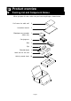
Product overview Packing List and Component Names When you open this box, make sure you have everything as shown below: Cuff cover for adult cuff 2 Instruction manual 1 Blood pressure recorder (Main unit) 1 Carrying case 1 Belt 1 Clip 1 Shoulder band 1 Adult cuff for left arm 1 Activity record sheet 10 Page 7
Name Power switch Functions This is the main power switch. At the OFF state, all data and parameters are stored by a backup battery. This backup battery life is approximately 10 days with the power off. AUTO ON/OFF key ・ When you press and hold the AUTO ON/OFF key, the automatic measurement is started or stopped alternately. ・ When you press the AUTO ON/OFF key at mode II of the automatic measurement, "S" is displayed or turned off alternately. This sign changes the interval for sleep.
Display Sleep sign Auto mode sign Low battery sign Full memory sign Sign A S B M Sign Setup sign of automatic measurement Systolic Blood Pressure display Diastolic Blood Pressure display Setup sign of display and clock Pulse display Error display ex. "Set the clock" Clock display Name Arrow Functions The arrow points to the kind of current display in the measurement result and function mode. Automatic "A" is displayed when the automatic measurement is selected.
Specifications Features Portability The recorder weighs approx. 215 g (including batteries) and is palm top size, because a micro-pump is used. The recorder is powered by LR6 type (Mignon) alkaline batteries. It is possible to replace the LR6 type batteries with Ni-MH rechargeable batteries. Operation & management Clock and automatic measurement parameters may be set as needed. If you connect to a computer and use the optional software, clock and automatic measurement parameters can be set easily.
Automatic measurement The measurement starts or stops using the AUTO ON/OFF key. When the measurement is started, the recorder begins to work in accordance with preset time intervals from the preset time of the internal clock. Refer to "Selection for the Automatic Measurement". In the automatic measurement, "A" appears in the upper left of the display.
ID number If you reset the recorder, the ID number is set to "1". The ID number can be set using the optional software.
Interface Connected to a computer, you can output the data and enter parameters. Connected to a printer, you can print the data.
The complete procedure for use Step by Step Procedure Step 1 Battery replacement. Replace with new alkaline batteries (note direction). Refer to "Replacing the Batteries" on page 16. Step 2 Turn on the recorder using the power switch. Step 2 Step 3 Follow the procedure, depending on the recorder state. Step 3 Case 1 Normal state The buzzer sounds once and the clock is displayed. The recorder is ready for use. The recorder stores parameters for "display and clock" and "automatic measurement".
Previous page Step 8 Attach the cuff to the patient. Refer to "Attaching the Cuff and Recorder". Step 8 Step 9 Attach the carrying case to the patient and insert the recorder. Refer to "Attaching the Cuff and Recorder". Step 9 Step10 Check the recorder using the manual measurement with Step 10 relaxed, but correct posture. Refer to "Manual Measurement". Step11 Start the automatic measurement. The recorder displays Step 11 "A" and starts the automatic measurement sequence.
Initializing the recorder Replacing the Batteries Caution When "B" is displayed before a measurement, the recorder cannot make a measurement. Please replace with new batteries before using. If "B" is displayed during the measurement, stop the measurement and replace with new batteries immediately. Use alkaline batteries or the specified rechargeable batteries for the recorder. Do not use new and used batteries at the same time. Steps for replacing the batteries Step 1 Open the battery cover.
The State of Turning on the Recorder There are three types of state when the recorder is turned on. Select an operation. Refer to "The complete procedure for use" about use. Action when the recorder is turned on. The buzzer sounds once and the clock is displayed. (Normal state) The buzzer sounds once and is displayed blinking. The buzzer sounds four times and is displayed blinking. State of recorder The recorder stores parameters for "display and clock" and "automatic measurement". All parameters are lost.
Steps for setting the display and clock This explanation uses the following examples. ex. After reset, the measurement value is not displayed. The clock is adjusted to 1997/ 05/ 27 14:28. Step 1 Press and hold the START STOP key for approx. 6 seconds. The recorder displays clock. START STOP for adjusting the display and AUTO ON/OFF Step 2 Press the AUTO ON/OFF key to display . (A selection to display the clock only in automatic measurement) Step 3 Press the START STOP key.
Selection for the Automatic Measurement This setting initializes measurement intervals that are based on the internal 24-hour clock. Mode mode I 07:00 ~ 21:59 22:00 ~ 06:59 The measurement is performed every quarter hour. The measurement is performed every half hour. mode II The AUTO ON/OFF key is pressed at rising and going to bed so that the measurement intervals are changed and the time during sleep can be distinguished on the data. When "S" is off, the measurement is performed every quarter hour.
Mode III Settings Setup procedure Before you enter into mode III, read the procedure below. Also, refer to the example on the next page for the setting procedure. Each block’s finish time is the next block’s start time. The end of block 6 automatically becomes the start time of block 1. If you enter the block 1 start time in any other block, these parameters are saved and this sequence is finished.
Steps for automatic measurement ex. First block 08:00 ~ 21:59 Second block 22:00 ~ 05:59 Third block 06:00 ~ 07:59 frequency 30 minutes frequency 60 minutes frequency 10 minutes Step 1 Press and hold the START STOP key for approx. 3 seconds. The current mode is displayed. START STOP Step 2 Press the AUTO ON/OFF key to display AUTO ON/OFF Step 3 Press the START STOP key. The mode is stored and the current start time of the first block is displayed.
From previous page Step13 Press the START STOP key. The current frequency of the third START STOP block is displayed. Step14 Press the AUTO ON/OFF key to display "10" for 10 minutes as the frequency of the third block. AUTO ON/OFF Step15 Press the START STOP key. The current start time of the fourth block is displayed. START STOP Step16 Press the AUTO ON/OFF key.
Deleting Old Data Caution Confirm that the data has already been transferred and saved, when the data is to be deleted. It is not possible to recover data that was deleted. It is not possible to delete data completely, if the START STOP key is released while the buzzer sounds at Step 2. Steps for deleting old data Step 1 Press and hold the START STOP key for approx. 9 seconds. If you want to cancel this process, press the AUTO ON/OFF key. is displayed.
Preparing the patient Patient Instructions Advise the patient on how to cope with mis-operation and contingencies. Precautions during automatic measurement Relax and be quiet, when the recorder starts inflating the cuff. Maintain the same posture during measurement. Avoid noises and vibrations during measurement. After inflation, the recorder deflates the cuff and measures the patient's blood pressure. The maximum measurement time is 90 seconds. Relax and be quiet during measurement.
Notes on Cuff Use Note: A cuff is a consumable item and may need replacing if worn or damaged. Please check the cuff conditions before use. In the following cases, replace the used cuff with a new one immediately. When there is a crack or stickiness in the joint of the cuff's bladder or the tube. When the tube is not flexible or has stiffened. When the surface of the tube is coated with an oil-like substance. When there is a defined crease in the bladder. Confirm the following before use.
Use of the Cuff Cover Step 1 Place the cuff on the cuff cover as shown. When the cuff cover with slits is used, pass the air hose through a slit. Step 2 Secure the cuff cover to the cuff using the fabric fasteners.
Steps for attaching the cuff and recorder Step 1 Make a circle where the end of the cuff is passed through the ring. Step 2 Search for the brachial artery using palpation. Step 3 Attach the cuff directly against the skin so that the artery position mark is directly over the brachial artery and the lower edge of the cuff is placed one inch above the inside of the elbow.
Preparation of the Carrying Case Use the belt or shoulder band to attach the carrying case. We recommend the belt so that the carrying case is not worn out of shape on the patient. Carrying case (IP02) Using the belt Step 1 Insert the belt through the strap located on the rear of the carrying case. Step 1 Step 2 Step 2 Pull the belt through the strap. Step 3 Pass the belt through the ring. Step 4 Pass the belt through the front-hole and the rear-hole of the hook.
Operation Automatic Measurement Caution Automatic measurement uses the internal clock and parameters for automatic measurement. Refer to "Parameters for the Display and Clock" and "Selection for the Automatic Measurement" for setting these parameters. When the patient stops the automatic measurement or removes the cuff, press and hold the AUTO ON/OFF key for approx. 3 seconds to turn off the "A" sign.
Data transfer The recorder transfers data to a printer or computer using the RS-232C terminal. We recommend analysis of the data using the optional analysis software. Caution Cover the RS-232C terminal using the cap, to prevent dust and foreign materials from entering when this terminal is not in use. Remove the recorder and cuff from the patient, when the recorder is connected to a printer or computer. The personal computer must comply with EN60601-1.
Steps for data transmission Step 1 Enter the parameters into the printer so that the data can be transmitted. Setup for printer Step 2 Connect the cable to both the recorder and printer. Then the recorder displays . Refer to "Analysis Software and Communication Cables" about the cable. Connection Step 3 Set the printer to "ON LINE". Step 4 Press the START STOP key. Then and the data is transmitted. Step 5 When the transmission is finished, displayed. Step 6 Remove the cable.
Data Transmission to a Computer Using Analysis Software Caution The recorder intensely consumes the battery power while connected to the RS-232C cable. Disconnect the cable when not actually transferring data. Maintain the power-on state while transmitting the data so that the data is not damaged. Steps for data transmission Step 1 Connect the cable to both the recorder and printer. The Connection recorder displays . Refer to "Analysis Software and Communication Cables" about the cable.
Options and accessories Analysis Software and Communication Cables The analysis software has functions as follows: Maximum value, minimum value and average are calculated in an arbitrary period of time. (Partial analysis) Correlation graph, trend graphis and histogram are displayed. The patient's data and information are managed. Data can be saved. Data can be deleted or copied. A saved data file can be exported into CSV format so that EXCEL can read it. Data can be output as a report.
Cuffs and Other Accessories Cuff Name Large cuff Adult cuff Small cuff Adult cuff for left arm, for left arm, for left arm, for right arm, 28 ~ 36 cm (11 ~ 14 inches) 20 ~ 31 cm ( 8 ~ 12 inches) 15 ~ 22 cm ( 6 ~ 8 inches) 20 ~ 31 cm ( 8 ~ 12 inches) Cuff cover Name Large cuff cover Adult cuff cover Small cuff cover Others Name TM-2430 Accuracy Diagnostic Kit Activity record sheet Carrying case (IP02) 10 sheets 10 sheets 10 sheets 10 sheets Page 34 Order code TM2430-02B TM2430-06B TM2430-07B TM2430-0
Maintenance Checking Accuracy Required equipment Accurate office mercury sphygmomanometer or aneroid gauge with inflation system. TM-2430 Accuracy Diagnostic Kit (TM2430-90). A rigid cylinder sized to fit the cuff pressured. Steps for checking accuracy Step 1 Turn off the TM-2430 and remove the air hose from the unit.
Cleaning the Cuff and Recorder Before cleaning the recorder, remove the battery cover, turn the power switch off and remove the batteries. The recorder is not water resistant. Do not allow liquids to splash on or get into the case while cleaning. After each use, wipe the case of the recorder with a clean lint free cloth, moistened with water and a mild detergent. Do not use antiseptic solutions, Alcohol, etc., to clean the recorder, hose or cuff.
Error Codes Caution Error code The error code may be updated without prior notice. Meaning No clock parameter E00 Status Operation and Treatment All parameters are lost. Enter clock parameters. Refer Reset status. to "Parameters for the Display and Clock" E03 Pressure zero error Low battery E04 An error code is displayed Release the air from the cuff without cuff inflation. completely. Measurement is stopped. Replace with new batteries. An error code is displayed.
Error code E30 Meaning Status Operation and Treatment Measurement time Air is exhausted from the cuff, and Repair is necessary because of exceeds 120 seconds. an error code is displayed. slow inflation or slow constant exhaust. E31 E32 E50 The constant exhaust Air is exhausted from the cuff, and Repair is necessary because of exceeds 60 seconds. an error code is displayed. slow constant exhaust. Clock error. An error code is displayed. If you cannot clear this error, repair is necessary.
Appendix EMC Information EMC guidelines and manufacturer’s declaration Medical Electrical Equipment needs special precautions regarding EMC and needs to be installed and put into service according to the EMC information provided in the following. Portable and mobile RF communication equipment (e.g. cell phones) can affect Medical Electrical Equipment.
Guidance and manufacturer’s declaration – electromagnetic immunity The A&D unit is intended for use in the electromagnetic environment specified below. The customer or the user of the A&D unit should assure that it is used in such an environment.
Guidance and manufacturer’s declaration – electromagnetic immunity The A&D unit is intended for use in the electromagnetic environment specified below. The customer or the user of the A&D unit should assure that it is used in such an environment. Immunity test IEC 60601 test level Compliance level Electromagnetic environment – guidance Electrostatic discharge (ESD) IEC 61000-4-2 ± 6 kV contact ± 6 kV contact ± 8 kV air ± 8 kV air Floors should be wood, concrete or ceramic tile.
Index Symbols ------------------------------------ 9 belt ------------------------------ 7, 8, 27 block------------------------ 2, 19, 20, 21 bpm ----------------------------------------2 ---------------------------------- 9 C ------------------------ 9 --------------------------------- 9 ---------------------------- 9 ---------------------------------- 9 ------------------------------- 9 ---------------------------------- 9 ---------------------------------- 9 ---------------------------------- 9 -----
left arm -------------------------------- 34 low battery ---------------------------- 9 SYS ----------------------------------------2 systolic blood pressure -- 2, 12, 37 M T M ------------------------------------- 9, 11 management ------------------------- 10 manual measurement ------------- 10 measurement ----------------------- 12 memory -------------------------- 11, 12 mode I -------------------------------- 19 mode II -------------------------- 19, 29 mode III -------------------------- 19, 20 tr
MEMO Page 44
1-243 Asahi , Kitamoto-shi, Saitama 364-8585, JAPAN Telephone: [81] (48) 593-1111 Fax: [81] (48) 593-1119 A&D INSTRUMENTS LIMITED Unit 24/26 Blacklands Way, Abingdon Business Park, Abingdon, Oxfordshire OX14 1DY United Kingdom Telephone: [44] (1235) 550420 Fax: [44] (1235) 550485 A&D ENGINEERING, INC. 1756 Automation Parkway, San Jose, California 95131, U.S.A.