Application Note: Zynq-7000 All Programmable SoC Video and Imaging Kit 1080p60 Camera Image Processing Reference Design XAPP794 (v1.3) December 20, 2013 Summary Authors: Mario Bergeron (Avnet, Inc.), Steve Elzinga, Gabor Szedo, Greg Jewett, and Tom Hill (Xilinx, Inc.
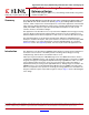
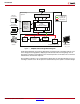
Introduction X-Ref Target - Figure 1 DDR3 Processing System Firmware on SD Card DDR Memory Controller S_AXI4_HPx M_AXI4_GP AXI4 Stream AMBA® Switches PC running Web-based GUI Hardened Peripherals (USB, GigE, CAN, SPI, UART, 12C GPIO) APU Dual Core Cortex-A9 + OCM AMBA Switches Camera Input Image Processing Pipeline AXI VDMA VITA-2000 Camera HDMI Output Programmable Logic HDMI Monitor X794_01_102512 Figure 1: 1080p60 Camera Design Block Diagram A web-based graphical user interface (GUI) al
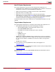
Introduction Host PC System Requirements The host PC requirements to operate the camera design and its applications are: • 32-bit/64-bit host PC with Ethernet port running Windows XP or Windows 7 Professional 32-bit/64-bit, or Ubuntu 10 or later 32-bit/64-bit Linux distribution. • UART connected terminal (for example, Tera Term 4.69 or HyperTerminal). • Zip/Unzip software (for example, 7-Zip). • Web browser such as Internet Explorer (to operate the web-based GUI).
Running the Demonstration Running the Demonstration This section describes how to run the 1080p60 camera image processing reference design on the ZVIK. Reference Design File The reference design files for this application note can be downloaded from: https://secure.xilinx.com/webreg/clickthrough.do?cid=199792 Table 1 shows the reference design matrix.
Running the Demonstration Preparing the SD Card Pre-built binaries for the camera design are provided in this directory: ..\zc702-zvik-camera\binaries\sd_content Create a backup copy of the files on the SD card provided with the kit to enable them to be restored if desired. These files are also available on the ZVIK product page. Copy the contents of the sd_content directory to the root directory of the SD card. By default, the design configures the ZVIK for IP address 192.168.1.10.
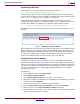
Running the Demonstration 9. Click the Subnet mask: field and ensure that it is populated with 255.255.255.0. The dialog box should appear similar to Figure 3. X-Ref Target - Figure 3 X794_03_102512 Figure 3: Host Computer IP Address Configuration Dialog Box 10. Select OK to close the Internet Protocol Version 4 (TCP/IPv4) dialog box. Select OK to close the Local Area Connection Properties dialog box. Assembling the Camera If the camera assembly has been completed, go to Setting Up the Hardware.
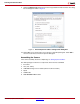
Running the Demonstration To assemble the camera: 1. Remove both protective caps from the lens (2) (Figure 4). X-Ref Target - Figure 4 5 4 2 6 3 1 X794_04_102612 Figure 4: VITA-2000 Camera Assembly Step 1 2. Attach the IR cut filter (1) to the lens (2) (Figure 5). The filter screws onto the front of the lens. X-Ref Target - Figure 5 4 5 3 6 X794_05_102612 Figure 5: XAPP794 (v1.3) December 20, 2013 VITA-2000 Camera Assembly Step 2 www.xilinx.
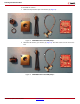
Running the Demonstration 3. Screw the IR cut filter and lens assembly onto the VITA-2000 image sensor module (3) (Figure 6). The image sensor module has a lens holder with an opening for standard C-mount lenses. X-Ref Target - Figure 6 4 5 6 X794_06_102612 Figure 6: VITA-2000 Camera Assembly Step 3 4. Attach the tripod (4) to the bottom of the VITA-2000 image sensor module (Figure 7).
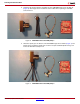
Running the Demonstration 5. Attach the LCEDI cable (5) to the back of the VITA-2000 image sensor module (Figure 8). Both ends of the LCEDI are identical. Either end can be connected to the image sensor module. X-Ref Target - Figure 8 6 X794_08_102612 Figure 8: VITA-2000 Camera Assembly Step 5 6. Attach the other end of the LCEDI cable to the FMC-IMAGEON FMC module (6) (Figure 9).
Running the Demonstration 7. The FMC-IMAGEON FMC Module connects to the FMC2 connector of the ZC702 board FMC carrier. The flexibility of the LCEDI cable allows the camera to be positioned in virtually any direction (Figure 10). X-Ref Target - Figure 10 X794_10_102612 Figure 10: XAPP794 (v1.3) December 20, 2013 VITA-2000 Camera Assembly Step 7 www.xilinx.
Running the Demonstration 8. The ZVIK package also contains two standoffs and four screws that secure the FMC-IMAGEON FMC module to the ZC702 board. The package also contains four longer screws, standoffs, and rubber feet to support the free end of the board. Assemble the hardware, as shown in Figure 11. X-Ref Target - Figure 11 X794_11_102612 Figure 11: VITA-2000 Camera Assembly Step 8 Setting Up the Hardware Figure 12 illustrates how to connect the ZVIK for the 1080p60 camera design.
Running the Demonstration Connect the ZVIK hardware as follows: 1. Position the Avnet FMC-IMAGEON board on the FMC slot #2 of the ZC702 board. 2. Connect the VITA-2000 camera to the FMC module with the provided LCEDI cable. 3. Connect the HDMI monitor to the ZC702 HDMI out connector (P1) with the provided HDMI cable. If a DVI monitor is used, an HDMI female to DVI-D male connector adapter must be provided. The connector adapter is available at most electronic retailers or through online sources. 4.
Running the Demonstration To view this serial output, open a terminal window using the UART connection program (Terra Term or Hyperterminal) with these settings: • 115200 baud • 8 data bits • No parity • 1 stop bit • No flow control To determine which host computer COM port is mapped to the ZC702 Silicon Labs driver, follow these steps (for Windows): Note: If not already installed, refer to the Zynq-7000 All Programmable SoC: ZC702 Evaluation Kit and Video and Imaging Kit Getting Started Guide (UG
Running the Demonstration To restart the boot process, press the POR_B button (SW1) located close to the SD card connector or power cycle the ZC702 board. This boot sequence should be observed: 1. The ZC702 board is powered on. 2. The DONE LED is off. 3. The first stage bootloader takes approximately 20 seconds. 4. Camera design hardware is loaded into programmable logic. 5. The DONE LED turns on. 6. U-Boot takes approximately 30 seconds. 7. Linux Kernel boot takes approximately 15 seconds. 8.
Running the Demonstration eth0, phy_addr 0x7, phy_id 0x01410e40 eth0, attach [Marvell 88E1116R] phy driver ++ Starting telnet daemon ++ Starting http daemon ++ Starting ftp daemon ++ Starting dropbear (ssh) daemon rcS Complete Finally, the camera demonstration software generates this output on the serial console: ------------------------------------------------------Xilinx Zynq-7000 EPP Video and Imaging Kit --1080P60 Real-Time Camera Demonstration ------------------------------------------------------FMC-
Running the Demonstration TPG 0 done TPG 1 done CFA done Initializing iPipe cores ... done! Configure ZC702 IIC Mux for Port 1 (HDMI) ... ZC702 HDMI Output Initialization ... web avnet console : IN(/tmp/zvik_camera_linux_pipe_req) OUT(/tmp/zvik_camera_linux_pipe_rsp) access(PIPE_IN_NAME, F_OK) ...done access(PIPE_OUT_NAME, F_OK) ...done open(PIPE_IN_NAME, O_RDONLY | O_NONBLOCK ) ...done [web_session_handler] ...
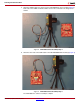
Running the Demonstration Adjusting the Lens The content captured by the image sensor and processed by the image processing pipeline should be visible on the monitor. If the image is blurry, adjust the lens focus, which ranges from 1 cm to 150 cm. If the image is too dark or too light, adjust the aperture (Figure 15). If the image is black, the aperture should be adjusted to allow more light to enter the image sensor.
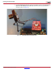
Running the Demonstration The FOV measurements are shown in Figure 16. X-Ref Target - Figure 16 H Field of View V L X794_16_102612 Figure 16: Determining the Required Field of View (FOV) A lens calculator (such as www.1stvision.com/lens/lens_calculator) can determine the FOV and, consequently, the ideal lens choice for a specific application. Using the Text-based Console The Linux camera demonstration application accepts commands from a text-based console.
Running the Demonstration cfa Color Filter Array Interpolation configuration stats|s Image Statistics awb Auto White Balance (on|off) agc Auto Gain Control (on|off) aec Auto Exposure Control (on|off) geq Gamma Equalization (on|off) noise Noise Reduction Threshold (0-255) enhance Edge Enhancement Threshold (0-32768) halo Halo Suppression Threshold (0-32768) ccm Color Correction Matrix configuration gamma Gamma Correction configuration Video Source Selection video Video Source Initialization and Selection (vi
Running the Demonstration Using the Web-based GUI To access the web-based GUI, open a web browser such as Internet Explorer and enter the ZVIK IP address http://192.168.1.10 (or the address assigned in Preparing the SD Card). The web page shown in Figure 17 appears. X-Ref Target - Figure 17 ; B B Figure 17: 1080p60 Camera Design Web-based GUI If the host computer cannot establish a connection, it might be necessary to disable virus scanning, the firewall, or both.
Running the Demonstration Adjusting the Image Sensor Gain and Exposure The image sensor gain and exposure can be adjusted using the controls shown in Figure 18.
Running the Demonstration The analog gain provides a course manual adjustment of the image sensor gain, as shown in Table 2. Table 2: Analog Gain Slider Settings Setting Description 0 Analog gain = 0.00 1 Analog gain = 1.14 2 Analog gain = 1.33 3 Analog gain = 1.60 4 Analog gain = 2.00 5 Analog gain = 2.29 6 Analog gain = 2.67 7 Analog gain = 3.20 8 Analog gain = 4.00 9 Analog gain = 5.33 10 Analog gain = 8.
Running the Demonstration Capturing a 1080P Image The Image Capture section of the web-based GUI allows capturing an image from the video frame buffer, as shown in Figure 19. X-Ref Target - Figure 19 X794_19_102612 Figure 19: Image Capture Controls After clicking Click to Take Snapshot, a scaled-down version of the image is displayed in the GUI.
Running the Demonstration Configuring the Color Filter Array Interpolation The Xilinx Color Filter Array Interpolation IP core Bayer Phase setting (Figure 21) can be changed, but only one setting produces a valid result with the VITA 2000 image sensor. X-Ref Target - Figure 21 ; B B Figure 21: Color Filter Array IP Core Control Image Enhancement The Xilinx Image Enhancement IP core reduces image noise and enhances the edges of objects in each picture.
Running the Demonstration The Halo Suppress slider contains the amount of halo suppression. The allowed values are from 0 to 32768, which is the integer representation of the range 0 to 1 using 16 bits with 15 fractional bits. Multiplication by 215 yields the integer representation. See Table 7. Table 7: Halo Suppression Settings Setting 0 1-32768 Description Halo Suppression OFF. Halo Suppression ON. Number identifies strength of halo suppression.
Running the Demonstration (Daylight, Cool White Fluorescent, U30, and Incandescent sources) with the color correction matrix set to Bypass (no color corrections applied). Average values for the 24 patches at each illumination setting were calculated by a MATLAB® software script. A second script is used to model the Xilinx color correction matrix operations and determine a set of coefficients that result in output from the color correction matrix that best matches the known target values for the 24 patches.
Running the Demonstration Configuring the Gamma Correction The gamma correction IP core is implemented as a look-up table that is applied to all three color channels. The gamma correction IP core can be adjusted using the GUI controls shown in Figure 25. X-Ref Target - Figure 25 X794_25_110513 Figure 25: Gamma Correction IP Core Controls The Gamma Table list box allows the manual gamma correction settings shown in Table 9.
Running the Demonstration Understanding the Image Statistics The Xilinx Image Statistics IP core provides hardware-based image analysis to support auto-focus, auto-exposure, and auto-white balance applications. The third column in the web-based GUI provides feedback from the image statistics IP core in the form of histograms, as shown in Figure 26. X-Ref Target - Figure 26 X794_26_110513 Figure 26: Histograms from the Xilinx Image Statistics IP Core Four histograms are displayed.
Running the Demonstration The intensity histogram (Figure 27) provides information about the overall image exposure.
Running the Demonstration The red histogram (Figure 29) shows the distribution of red pixel values. X-Ref Target - Figure 29 X794_29_110513 Figure 29: • Red Histogram A red bar on the top right indicates that the red color channel is over-saturated according to the formula: (number of pixels in the 242–255 range) > 0 • A green bar on the top indicates that the red color channel is not over-saturated. The green histogram (Figure 30) shows the distribution of green pixel values.
Hardware Platform • A green bar on the top indicates that the blue color channel is not over-saturated. The contents of the histograms are static by default, unless configured otherwise. There are two options for updating the histograms (see Figure 28): 1. To update the contents of the histograms a single time, click Update. 2. To periodically update the histograms, click Click to Start. To stop periodically updating the histograms, click Click to Stop.
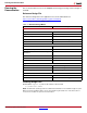
Hardware Platform This design is implemented in a Zynq-7000 AP SoC device (XC7Z020CLG484-1) using Vivado 2013.2 design tools. The PL hardware utilization for the implemented design is shown in Table 10. Table 10: Hardware Utilization FPGA Components Total Available Used % Used I/Os 200 58 29 LUTs 53,200 30,614 57 Registers 106,400 38,316 36 DSP48s 220 92 42 RAMB36E1/FIFO36E1s 140 36 26 RAMB18E1/FIFO18E1s 280 16 6 Block RAM Notes: 1.
Hardware Platform Programmable Logic • One 64-bit AXI interconnect at 148.5 MHz • One 32-bit AXI interconnect at 50 MHz • VITA receiver (serial LVDS) interface • Image processing pipeline • Video frame buffer (AXI-VDMA) • HDMI output interface Device Address Map The pcores that are instantiated on the M_AXI_GP0 port are shown in Table 11. Table 11: AXI GP0 Address Map Instance Peripheral Base Address High Address v_spc_1 Defective Pixel Correction (7.
Hardware Platform The clock signals are shown in Table 12. Table 12: System Clocks Clock Signal Frequency (MHz) Source Use clk_50MHz PS – FCLK0 50 AXI4-Lite interconnect clock. clk_200MHz PS – FCLK1 200 200 MHz reference clock for deserializer in VITA receiver. fmc_imageon_video_clk1 External video clock coming from clock synthesizer on FMC module 148.5 Input clock to clock generator. vid_out_clk Clock generator – MMCM (1) 148.
Hardware Platform In this design, the stream interface data width is set to 32 bits and the memory-mapped interface width is 64 bits. The AXI VDMA is used in simple register direct mode, which removes the area cost of the scatter gather feature. Initialization, status, and management registers in the AXI VDMA core are accessed through an AXI4-Lite slave interface. To get the best possible throughput for AXI VDMA instances, the maximum burst length is set to 16.
Hardware Platform This core is responsible for correcting defective pixels, as illustrated in Figure 36. X-Ref Target - Figure 36 X794_36_110513 Figure 36: Defective Pixel Correction For additional information about the Defective Pixel Correction LogiCORE solution and the detailed product guide, see the Defective Pixel Correction product page: www.xilinx.
Hardware Platform Image Statistics Engine The AXI STATS core is used to gather various image statistics from the image processing pipeline (Figure 39) such as: • Intensity histograms • Color histograms X-Ref Target - Figure 39 AXI TPG AXI DPC AXI TPG AXI CFA AXI CCM AXI Stats AXI Gamma AXI RGB2YUV AXI Enhance Chroma Resampler X794_39_110513 Figure 39: AXI Stats Core Pipeline Position For additional information about the Image Statistics Engine LogiCORE solution and the detailed product guid
Software Platform Color Correction Matrix The AXI Color Correction Matrix (CCM) core is used to implement various color corrections in the image processing pipeline (Figure 42): • White balance • Brightness • Contrast • Saturation AXI CFA AXI TPG X-Ref Target - Figure 42 AXI TPG AXI DPC AXI CCM AXI Stats AXI Gamma AXI RGB2YUV AXI Enhance Chroma Resampler X794_42_110513 Figure 42: AXI CCM Core Pipeline Position For additional information about the Color Correction Matrix LogiCORE solutio
Software Platform The block diagram in Figure 44 illustrates the general architecture of the Linux application. X-Ref Target - Figure 44 STDIN STDOUT To/From Web Server (Named Pipes) Main Task Web Session Task avnet_console Image Statistics Task fmc_imageon_demo video_ipipe fmc_imageon vita_receiver zvik_camera_linux_app.elf X794_44_110513 Figure 44: 1080p60 Camera Linux Application General Architecture The application has three tasks: 1. Main Task (main.c) 2.
Software Platform The block diagram in Figure 45 shows the source files that make up the 1080p60 camera application.
Software Platform Main Task The main task is the main( ) function, which initializes the reference design. This function also: • Initializes the VITA image sensor • Initializes the image processing pipeline • Initializes the video frame buffer • Launches the other tasks (image statistics task, web session task) When the reference design has been initialized, it provides a text-based command interface via the STDIN and STDOUT pipes. The main.
Software Platform Figure 46 illustrates how the image statistics handler interacts with the image processing pipeline.
Rebuilding the Hardware Platform Web Session Task The web-based GUI is implemented with several applications. Figure 47 illustrates how these applications interact with each other. X-Ref Target - Figure 47 Web Server Web Pages zvik_camera_linux_webserver.elf STDIN STDOUT Image Statistics Task Main Task Names Pipes Web Session Task zvik_camera_linux_app.
Rebuilding the Hardware Platform In Vivado 2013.2, the Video and Image Processing Pack does not include licenses for these cores: • Test Pattern Generator • RGB to YCrCb Color-Space Conversion These cores must be requested in addition to the Video and Image Processing Pack. 3. Select the Add Evaluation and No Charge IP Cores page to request licenses for the Video and Image Processing Pack, as well as the Test Pattern Generator, and RGB to YCrCb cores, as shown in Figure 49.
Rebuilding the Hardware Platform 4. The generated license file is sent by email. Follow the enclosed instructions to add the evaluation license features for the Video and Image Processing Pack. Build the Hardware Design Bitstream 1. Launch Vivado 2013.2: • On a Windows host, select Start > All Programs > Xilinx Design Tools > Vivado 2013.2 > Vivado 2013.2 • On a Linux host, enter vivado at a command prompt. 2.
Rebuilding the Hardware Platform 3. Once the bitstream is created, select Open Implemented Design and click OK (see Figure 51). X-Ref Target - Figure 51 ; B B Figure 51: Bitstream Generation Completed Exporting the Base Hardware Platform to SDK Because the base hardware platform is used with the software development kit (SDK), information about the hardware platform must be provided to the SDK to allow development of software platforms and applications. 1.
Rebuilding the Software Applications 3. If you have not saved the IP Integrator block diagram, save it before exporting the hardware for SDK (Figure 53). Click Save.
Rebuilding the Software Applications Note: The projects in the import wizard might appear in a different order than that shown in Figure 54. X-Ref Target - Figure 54 ; B B Figure 54: Importing Linux Applications 5. Click Finish. The SDK tool imports the selected projects. The software application is compiled during the import process. Debugging the Linux Application Before starting a remote debug session with the ZVIK, make sure the Linux application is NOT running on the ZVIK: 1.
Rebuilding the Software Applications 4. Optionally, to permanently prevent the application from auto-starting on boot, edit the init.sh script on the SD card and comment out the statement shown using the “#” character: zynq> vi /mnt/launch_my_app.sh # /mnt/zvik_camera_linux_app.elf A remote connection can be established between the SDK tool and the ZVIK using Secure Shell (SSH) by following these steps: 1. In the SDK tool, select Window > Open Perspective > Other …. 2.
Rebuilding the Software Applications 3. Right-click and select Debug As. 4. Select Debug Configurations…. 5. In the Debug Configurations dialog box, select Remote ARM Linux Application, then click the new launch configuration button, as shown in Figure 56. X-Ref Target - Figure 56 X794_56_102612 Figure 56: New Launch Configuration Button 6. In the Connection list, select the ZVIK IP address (i.e., 192.168.1.10). 7.
Rebuilding the Software Applications 12. Click the display selected console button, and select the zvik_camera_linux_app.elf entry, as shown in Figure 58. X-Ref Target - Figure 58 X794_58_102612 Figure 58: Display Selected Console 13. Click the Resume button (or press F8). The console output shown in Figure 59 is displayed. X-Ref Target - Figure 59 X794_59_102612 Figure 59: Example Console Output 14. Add this breakpoint: • Source file: avnet_console.c • Function: avnet_console_record_command 15.
Rebuilding the Software Applications 17. Search for the avnet_console_record_command function, then double-click the left margin to enable a breakpoint. Select the command Search > C/C++ Search and enter the function name. The search results appear in a new tab in a window below the source window (see Figure 60). X-Ref Target - Figure 60 X794_60_102612 Figure 60: Breakpoint Search Results 18. Switch back to the Debug perspective. 19. On the console, type rec /mnt/image1.bmp, then press enter.
Preparing the SD Card Boot Image Preparing the SD Card Boot Image To configure and boot the ZC702 board with a customized hardware design and Linux platform, the ISE tools and provided script files should be used to prepare the image files described in Table 14. Table 14: ZC702 Evaluation Board Image Files Image Name Description BOOT.BIN The zynq_fsbl.elf, u-boot.elf, and system.bit files combined and renamed BOOT.BIN to satisfy licensing requirements. init.
Preparing the SD Card Boot Image Regenerating the BOOT.BIN File The BOOT.BIN file can be regenerated using the SDK tool by following these steps: 1. In the SDK tool window, select Xilinx Tools > Create Boot Image (see Figure 61). X-Ref Target - Figure 61 X794_61_111512 Figure 61: Create Zynq Boot Image Dialog 2. Click the Browse button under the Basic tab adjacent to the FSBL elf entry. 3. Select the C:\zc702-zvik-camera\binaries\boot_image\fsbl.elf file and click Open. 4. Click the Add button. 5.
Appendix Linux Kernel Image and Linux Root File System It is beyond the scope of this application note to provide instructions for regenerating the Linux kernel image and the Linux root file system. It is assumed that the Linux root file system is created as described here: wiki.xilinx.com/zynq-rootfs or use the pre-built RAM disk image available here: xilinx.wdfiles.com/local--files/zynq-release-14-2/14.2-release.tar.gz Appendix Table 15 lists the acronyms used in this application note.
References Zynq-7000 All Programmable SoC Documents and Links 1. Zynq-7000 All Programmable SoC ZC702 Evaluation Kit documentation page: www.xilinx.com/support/documentation/zc702 2. Xcell Journal, Issue 81, Fourth Quarter 2012 www.xilinx.com/publications/archives/xcell/Xcell81.pdf#Oct12NL 3. UG585, Zynq-7000 All Programmable SoC Technical Reference Manual 4. DS406, LogiCORE IP Processor System Reset Module Product Specification 5. DS768, LogiCORE IP AXI Interconnect 6.
References Video Documents 25. PG001, LogiCORE IP Color Correction Matrix Product Guide 26. PG002, LogiCORE IP Color Filter Array Interpolation Product Guide 27. PG003, LogiCORE IP Image Edge Enhancement Product Guide 28. PG004, LogiCORE IP Gamma Correction Product Guide 29. PG005, LogiCORE IP Defective Pixel Correction Product Guide 30. PG008, LogiCORE IP Image Statistics Product Guide 31. PG011, LogiCORE IP Image Noise Reduction Product Guide 32. PG012, LogiCORE IP Chroma Resampler Product Guide 33.
Revision History Revision History The following table shows the revision history for this document. Date Version Description of Revisions 11/22/2012 1.0 Initial Xilinx release. 11/29/2012 1.1 Removed references to targeted reference design (TRD). Updated Figure 52, page 46 and Figure 53, page 47. Updated the path for the hardware description files and Zynq device initialization C source code in Exporting the Base Hardware Platform to SDK, page 46. Added path for system.