
User manual


Running the Demonstration
XAPP794 (v1.3) December 20, 2013 www.xilinx.com 12
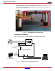
Connect the ZVIK hardware as follows:
1. Position the Avnet FMC-IMAGEON board on the FMC slot #2 of the ZC702 board.
2. Connect the VITA-2000 camera to the FMC module with the provided LCEDI cable.
3. Connect the HDMI monitor to the ZC702 HDMI out connector (P1) with the provided HDMI
cable. If a DVI monitor is used, an HDMI female to DVI-D male connector adapter must be
provided. The connector adapter is available at most electronic retailers or through online
sources.
4. Connect the USB-Serial port on the ZC702 board (J17 labeled USB UART) to the host
computer using the provided USB Mini-B to USB-A cable.
5. Connect the Gbit Ethernet connector on the ZC702 to the host computer using the
provided Ethernet cable.
6. Ensure that the power switch on the ZC702 board is off by moving the switch away from the
power connector.
7. Connect the 12V power supply to the ZC702 board.
8. Insert the SD card into the ZC702 board SD card connector.
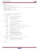
9. Ensure that the switches are set as shown in Figure 13, allowing the ZC702 board to boot
from the SD-MMC card.
10. Ensure that the monitor is set for HDMI (or DVI if using an HDMI female to DVI-D male
adapter) at 1920 x 1080 resolution.
11. Power on the ZC702 board.
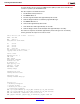
Observing the Linux Console on the Serial Port
During boot, the Zynq-7000 SoC displays these steps on its serial port:
• First stage boot loader (FSBL) output
• U-Boot output
• Linux console output
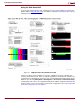
X-Ref Target - Figure 13
Figure 13: Switch Settings for the SD-MMC Card Boot Mode Switch
X794_13_102612