PORTABLE GENERATOR Owner’s Manual GXS4300i DO NOT RETURN TO STORE! CALL US FIRST 855-888-3598 FOR SUPPORT Model: Serial: Date Purchased: P/N: 32082-00000-00 Model# 1492001 REV00 SAVE THIS MANUAL FOR FUTURE REFERENCE
Table of Contents Introduction..........................................1 Maintenance And Storage....................20 Safety....................................................1 Maintenance Schedule.........................20 General Safety Precautions....................2 Engine Maintenance.............................20 Unpacking the Generator.......................7 Engine Oil Level Check.........................20 Parts Included........................................7 Change Engine Oil......
INTRODUCTION Read This Manual Thoroughly WARNING Read and understand manual completely before using product. Failure to completely understand manual and product couldresult in death or serious injury. If any section of this manual is not understood, contact customer Service at 855-888-3598, or www.a-ipower.com for starting, operating and servicing procedures. The owner is responsible for proper maintenance and safe use of the unit. SAVE THESE INSTRUCTIONS for future reference.
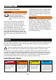
Asphyxiation Hazard Electric Shock Hazard Fire Hazard Explosion Hazard Hot Surface. Do Not Touch the Surface. Burn Hazard Moving Parts Hazard Kickback Operator’s Manual GENERAL SAFETY PRECAUTIONS Using a generator indoors CAN KILL YOU IN MINUTES. Generator exhaust contains carbon monoxide. This is a poison you cannot see or smell. NEVER use inside a home or garage, EVEN IF doors and windows are open. Only use OUTSIDE and far away from windows, doors and vents. Avoid other generator hazards.
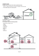
CORRECT USAGE Example location to reduce risk of carbon monoxide poisoning • ONLY use outside and downwind, far away from windows, doors and vents. • Direct exhaust away from occupied spaces.
NOTICE WARNING Starter cord kickback (rapid retraction) will pull hand and arm toward engine faster than you can let go which could cause broken bones, fractures, bruises, or sprains resulting in serious injury. • When starting engine, pull cord slowly until resistance is felt and then pull rapidly to avoid kickback. • NEVER start or stop engine with electrical devices plugged in and turned on. DANGER Fuel and its vapor are extremely flammable and explosive. Add fuel in a well ventilated area.
DANGER Contact with terminals, bare wires and electrical connections when generator is running will result in death or serious injury. DANGER Fire and electrocution hazard. Do not connect to a building's electrical system unless the generator and transfer switch have been properly installed and the electrical output has been verified by a qualified electrician. The connection must isolate the generator power from utility power and must comply with all applicable laws and electrical codes.
• DO NOT tamper with governor spring, links or other parts to increase engine speed. Generator supplies correct rated frequency and voltage when running at governed speed. • DO NOT modify generator in any way. NOTICE Exceeding generators wattage/amperage capacity could damage generator and/or electrical devices connected to it. • DO NOT exceed the generator’s wattage amperage capacity. • Start generator and let engine stabilize before connecting electrical loads.
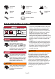
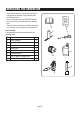
UNPACKING THE GENERATOR • Open carton completly. Remove and verify carton content prior to assembly. Your generator ships with following items. • Call our customer service at 855-888-3598 with the unit model and serial number for any missing item. • Record model, serial number, and date of purchase on front cover of this munual for your own record. Parts Included Your gasoline powered generator ships with the following parts: 1 2 4 3 NO.
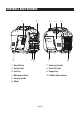
CONTROLS AND FEATURES 1 6 2 3 7 8 4 5 9 1 - Recoil Starter 7 - Telescopic Handle 2 - Control Panel 8 - Panel LED Light 3 - Fuel Cap 9 - Support Leg 4 - Maintenance Cover 10 - Muffler/Spark Arrester 5 - Carrying Handle 6 - Wheel Page 08 10
CONTROL PANEL FEATURES 1 2 3 4 5 5 6 12V 11 10 9 8 1. LED DATA CENTER: See LED DATA CENTER section. 2. CO (Carbon Monoxide) WATCH-GUARD Indicator Light (Red for Shut off and Yellow for Service): The CO(Carbon Monoxide) WATCH-GUARD monitors for the accumulation of poisonous CO gas around the generator produced by engine exhaust when the generator is running. If the CO WATCH-GUARD detects increasing levels of CO gas, it automatically shuts off the engine.
CONTROL PANEL FEATURES LED Data Center 1 2 3 4 1. LED Multi-Meter: Displays voltage,power,fuel level, frequency, and running time. 2. Low Idle Push Button: Low idle minimizes the fuel consumption and noise by adjusting the engine speed to the minimum required for the current load. 3. Low Oil Indicator LED(Red): Illuminates when the engine oil level falls below the safe operating level and the generator will automatically shut off the engine.
SPECIFICATIONS GXS4300i Model Number 1492001 Starting Watts 4300W Running Watts 3450W Rated AC Voltage 120V Rated DC Voltage 5V/12V Rated Frequency 60HZ Phase Single Grounding System (AC) Engine Type Neutral Floating Single Cylinder, 4-Stroke OHV Air Cooled Engine Displacement 149cc Starting System Recoil Low Oil Shutdown Oil Type Oil Capacity Spark Plug OEM Type Spark Plug Replacement Type Spark Plug Gap Yes 10W-30 16.2 fl.oz (0.48 L) A5RTC CR5HSA or equivalent 0.028~0.031inch (0.7~0.
CO WATCH-GUARD Carbon Monoxide (CO) Detection and Auto Shutoff System Your Generator is equipped with Carbon Monoxide (CO) WATCH-GUARD detect system for your protection and safety. This detecting and shutoff system monitors for the accumulation of poisonous CO gas around the generator produced by engine exhaust when the generator is running. If the CO sensor detects increasing levels of CO gas, it automatically shuts off the engine.
2-Blinking Yellow Light provides notification that a CO WATCH-GUARD fault has occurred and no longer provides protection. The generator is shutoff automatically and the yellow light will blink for at least five minutes after shutoff. Call A-iPower Customer Service 855-888-3598 for repair. Do not use the generator until the sensor is working properly. The CO WATCH-GUARD must only be serviced by qualified technician to restore it to original settings.
Add Engine Oil We recommend using SAE 10W-30 APISJ oil for best performance. Other high-quality detergent oils (APISJ or higher) are acceptable. Do not use special additives. Ambient temperature determines the proper oil viscosity for the engine. Use the chart to select the proper oil for the outdoor temperature range expected. NOTICE The unit is equipped with a low oil shutdown. If the oil level becomes lower than required, the sensor will activate a warning device or stop the engine.
• DO NOT mix oil in gasoline. • DO NOT modify engine to run on alternate fuels. Operation at High Altitude WHEN ADDING FUEL • Fill fuel tank outdoors. • DO NOT overfill tank. Allow space for fuel expansion. If the tank is overfilled, fuel can overflow onto a hot engine and cause fire or explosion. • If fuel spills, wait until it evaporates before starting engine. • Keep fuel away from sparks, open flames, pilot lights, heat, and other ignition sources.
OPERATION Generator Location Surge suppressors come in single- or multi-outlet styles. They’re designed to protect against virtually all short-duration voltage fluctuations. WARNING Make sure you review each warning in order to prevent fire hazard. Using a generator indoors CAN KILL YOU IN MINUTES. Generator exhaust contains carbon monoxide. This is a poison you cannot see or smell. NEVER use inside a home or garage, EVEN IF doors and windows are open. Starting the Generator 1.
6. Turn the starting dial switch to the RUN position. 1. Let engine stabilize and warm up for a few minutes after starting. 2. Ensure circuit breaker on control panel is in on position. 3. Plug in and turn on the desired 120 Volt AC, single phase, 60Hz electrical loads. It is better to attach the item with largest load first.
at maximum power and speed (RPM), push the LOW IDLE Switch to the OFF position. Stopping the Engine 1. Turn off and remove entire electrical loads. Never start or stop the generator with electrical devices plugged in or turned on. Let the generator run at no-load for two minutes to stabilize internal temperatures of the engine and generator. 2. Turn the starting dial switch to the OFF position. 2. Restart engine and if the engine stops again a low oil condition may still exist.
Set up and Operation 1. Align the two inverters on a firm, flat and level surface at a minimum 20 inch apart. WARNING If not spaced apart, the exhaust heat from one generator discolors or melt the plastic shell on other generator. 4. The parallel operation outlets allow you to connect two AIPOWER generators to increase the total available electrical power. The AIPOWER Parallel Operation Kit can be purchased.
MAINTENANCE AND STORAGE MAINTENANCE SCHEDULE Regular Maintenance will improve the performance and extend the life of your generator. Follow maintenance schedule intervals whichever occurs first according to use. NOTE: Adverse conditions will require more frequent services. Walk-Around Inspection Before starting the engine perform a visual inspection of the unit.
Recommended Engine Oil Type CAUTION 10W-30 5W-30 10W-40 5W-30 Full Synthetic ° F -20 °C -28.9 0 -17.8 20 -6.7 40 4.4 60 15.6 80 26.7 100 37.8 120 48.9 Ambient temperature Check the engine oil level before each use or every 8 hours of operation. 1. Place the generator on a level surface and allow the engine to cool for several minutes. 2. Loosen the bolts and remove the oil access cover. 3. With a damp rag, clean around the oil dipstick. 4. Remove the oil dipstick. 5.
6. Measure plug gap. The correct gap is 0.028-0.031 in. (0.7-0.8 mm). To widen gap, if necessary, carefully bend the ground (top) electrode. To lessen gap, gently tap ground electrode on a hard surface. 7. Seat spark plug in position; thread in by hand to prevent cross-threading. 8. Tighten with wrench to compress washer. If spark plug is new, use 1/2 turn to compress washer appropriate amount. If reusing old spark plug, use 1/8 to 1/4 turn for proper washer compression.
Short Term Storage Fill the tank with fresh gasoline and add gasoline stabilizer. Drain the carburetor float bowl. 1 - Add a properly formulated FUEL STABILIZER to the tank if it is not already added. 2 - Run the engine for 10-15 minutes to circulate stabilizer throughout fuel system. 3 - Allow the generator to cool a minimum of 30 minutes and then drain the carburetor float bowl. 4 - Clean the generator and store in a cool, dry and well ventilated area out of direct sunlight.
DRAINING THE FLOAT BOWL 1. Turn the fuel tank valve to the OFF position. 2. Locate the drain screw on the bottom of the carburetor float bowl. 3. Place an appropriate gasoline container to catch the drained fuel. 4. Loosen the float bowl drain screw and allow the fuel to drain from the drain tube. Tighten the float bowl drain screw. DANGER Explosion and Fire. Fuel and vapors are extremely flammable and explosive. Store fuel in a well ventilated area. Keep fire and spark away.
TROUBLE SHOOTING PROBLEM POSSIBLE CAUSE SOLUTION Engine is running, but no AC output is available. 1. AC Circuit breaker is open. 2. Fault in generator. 3. Poor connection or defective cord set. 4. Connected device is bad. 5. GFCI outlet is open (if equipped) 1. Check AC load and reset circuit breaker. 2. Contact customer service or authorized service center. 3. Check and repair. 4. Connect another device that is in good condition. 5. Correct ground fault and press reset button on GFCI outlet.
1 2 54 3 4 11 10 8 9 7 6 5 12 13 14 22 18 19 20 21 15 41 42 43 44 45 46 47 48 49 16 23 40 24 25 17 39 38 26 27 28 37 29 36 52 51 50 43 30 35 10 31 32 34 1 8 1 10 33 53 1 Page 26 GXS4300i PARTS DIAGRAM AND PARTS LIST PARTS DIAGRAM 55 56
Parts List NO. Part Number Description Qty. NO. Part Number Description Qty. 1 30111-00083-00 Philips screw M5*14 24 39 33004-01223-00 Engine mounting bracket 1 2 30111-00008-00 Philips screw M5*10 5 40 30101-00349-00 Hex flange bolt M6*40 2 3 30111-00023-00 Philips screw M4*12 1 41 34024-00085-00 Clip nut M6 6 4 31026-00388-00 Switch knob 1 42 33089-00511-00 Base plate 1 5 20114-07144-00 Panel assy.
Page 28 ENGINE Trigger Stepping motor Main coil Sub coil DC coil L OR CO sensor module Y W B Br O R/W Ignition coil BL R Y Control module Low oil shutdown module (sensor) B Br R/W B L LP B B B W B voltage regulator L rectifier W R L DC Grounding system(AC): Neutral Floating CIRCUIT DIAGRAM 9A W B G/W G B/W 12V B/W B/W O L L/W Br W B R DC 12V O L W B B:BLACK G:GREEN Br:BROWN Gy:GRAY B W USB Gy Y R - G + W G/W 20A 30A G/Y LED light Parallel outlets L:BLUE
WARRANTY LIMITED WARRANTY KEEP YOUR RECEIPT. Proof of purchase will be required to substantiate any warranty claim. WHAT IS COVERED: A-iPower Corp.
other force majeure events beyond the control of the manufacturer. Warranty limits and Implications and Consequential Damages A-iPower is not obligated to cover any loss of time, use of product, freight cost, or any other incidental or consequential claim from the use of this product. This warranty is in Lieu of all other warranties, express or implied. This warranty gives you specific legal rights which vary from state to state.
Fontana, CA 92337 USA Phone: 855-888-3598 support@a-ipower.com www.a-ipower.
A-iPOWER WARRANTY REGISTRATION FORM Register your product by emailing this form to support@a-ipower.com or register on-line at: www.a-ipower.com. Registering your product is important , it provides the following protections: 1. You have record of product purchased 2. Customer Service can Better serve you for Warranty related issues 3.
Fontana, CA 92337 USA Phone: 855-888-3598 support@a-ipower.com www.a-ipower.