Master-8 Instruction Manual Thank you for buying Master-8. Master-8 is an 8-channel pulse generator, based on advanced microprocessor technology. Master-8, the flexible pulse generator, has many useful features. You will find that Master-8 is user friendly and the programming simple and easy to learn. Master-8 is an attractive unit and you will enjoy using its eight paradigms.
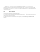
Table of Contents 1. Introduction 1.1 General 2. Front and Rear Panel Description 2.1 Front Panel 2.2 Rear Panel 3. Theory of Operation 4. Operation 4.1 Parameters 5. Applications 6. Programming Master-8 7. Modes of Operation 7.1 Setting the modes of Operation 8. Setting Parameters 8.1 Using the ‘’ and ‘↓’ Keys 8.2 Setting the ‘M’ Parameter 8.3 Counting the Pulses 9. Triggering 9.1 Manual Triggering 9.2 Setting the internal connections: 9.3 External Inputs 10. Eight Stored Paradigms 10.
Appendix A - Pin Connections Appendix B - Setting the baud-rate and character format Appendix C - Key Codes Appendix D - Notes for programming the Master-8-cp by a computer 1. Introduction Master-8 is an 8-channel stimulator/pulse generator which enables you to switch your set-up between completely different experiments (paradigms). Master-8 stores eight user’s preprogrammed paradigms. Each paradigm can use all eight channels.
2. 2.1 Front and Rear Panel Description Front Panel The Front Panel contains four main sections: − − − − Power Switch and Power On Indicator Front Panel keys Input Section Output Section One. Power Switch and Power On Indicator: The power switch and the power ON indicator are located on the lower left side of the front panel. Two. Front Panel Keys The front panel keys are color-coded and comprise 5 groups as follows: 1. Digits: 0 to 9. 2. Operation mode keys: FREE (Free Run), TRAIN, TRIG, DC, GATE, OFF.
Outputs ‘2+3’, ‘4+5’ and ‘6+7+8’ are the summations of outputs ‘2+3’, ‘4+5’ and ‘6+7+8’ respectively. You can use these sockets for multi-level pulses (e.g. +/- pulses). The two switches add the summations ‘2+3’ and /or ‘6+7+8’ to the ‘4+5’ output, resulting in the ‘4+5’ output delivering up to 7 pulse levels +GND. 2.2 Rear Panel The rear panel contains the following components: a. A switch to connect or disconnect the ground to/from the chassis. reduce the noise level of the system.
3.
4. Operation Master-8 is simple to operate and can be learned in a short time. Each instruction is carried out only after pressing the ENTER key. As long as the ENTER key has not been pressed, the instruction can be changed or deleted by giving new instructions (e.g. the ClearDisplay instruction). If you insert an illegal instruction, an error message appears on the display and the unit does not accept this instruction. 4.
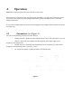
5. Applications Figure 2 shows you how Master-8 works. Do not try to follow the programming yet, it is explained in Section 6. Notes: ➀ Triggered externally or manually (by one keystroke) ➁ Turned on and off manually (by one keystroke). Figure 2.
USE BY #3 FREE-RUN duration. Interval none #2 TRIG duration, delay #3 #4 TRAIN duration, interval, M #2 & #3 #5 DC none none A special feature of Master-8 is the 3 multilevel outputs which you can use for multilevel pulses (e.g. +/- pulses). These OUTPUTS are ‘2+3’, ‘4+5’ and ‘6+7+8’ respectively. Close to the ‘4+5’ output there are two switches.
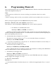
6. Programming Master-8 This section demonstrates how to program the Master-8. Please follow the instructions and notice how simple and straightforward they are. Notes: 1. Each instruction is followed by a reference enabling you to find more details on a similar instruction. 2. Before continuing, make sure that you are familiar with the location of different keys (see item 2.1). Before you begin to program, the entire Master-8 memory must cleared.
b) EXTERNAL TRIGGERING Whenever there is an input pulse in the ‘EXT 2’ input it triggers channel #2 (see Section 9). c) INTERNAL TRIGGERING You can internally connect each channel to any number of the other channels (see Section 9). 4. Connect channel #1 internally to channel #2 Press keys: ‘CONNECT,1,2,ENTER’ to connected. (see Section 9). Each output of channel #1 triggers channel #2. Notes: One.You don’t have to worry about the amplitude or polarity of the trigger source. Two.
10. Connect channel #1 to trigger #3. Press keys: CONNECT,1,3,ENTER (see Section 9). Channel #1 will now trigger both channels #2 & #3. Note: The ‘→’ sign on the panel above the ‘1.4’ digits. This arrow indicates the direction of the connection. To demonstrate Master-8’s most powerful feature Assume that you programmed all the 8 channels to run in a specific pattern (your present experiment) and now you want to switch to a new pattern (PARADIGM) that also uses all the 8 channels.
after 7 years). 15. Switch the power on. Master-8 immediately continues working in the last paradigm, exactly as before you switched the power off. 16. Switch to paradigm #1. Press keys: ‘ALL,1,ENTER’. Note: this paradigm is also stored in the memory after switching the power off. 17. Before continuing, clear all the Master-8 memory Press keys: ‘OFF,ALL,ALL,ALL,ENTER’. (see Section 10). Dear User, The last section was a brief demonstration of how to use Master-8.
7. Modes of Operation Each of the 8 channels can operate in one of the following modes: Mode Description FREE RUN The channel delivers pulses continuously according to the programmed duration and interval times. The channel is independent of the other channels. TRAIN Following a trigger, the channel delivers a train of pulses according to the programmed duration and interval times. The number of pulses per train is set by ‘M’.
Press keys: ‘TRAIN,3,ENTER’. Channel #3 is now in the TRAIN mode. You can trigger it in several ways. Trigger it now manually by pressing ‘3’ (channel number) Example 3: To set channel #5 in the DC mode Press: ‘DC 5 ENTER’ Channel #5 is now in the DC mode, it is time independent and delivers a continuous pulse. You can manually stop and start the pulse by pressing ‘5’ (channel number) Example 4: To turn off all the channels Press keys: ‘OFF,ALL,ENTER’.
8. Setting Parameters To set the time parameters (DURA, DELAY or INTER), first press the selected parameter key and then the desired time. Example: To set the duration of channel 6 to be 52 msec (52 x 10-3 sec, the time is given in seconds). Press keys: ‘DURA,6’ (the previous duration is displayed. If the duration time has never been set, the sign ‘FFFF FF’ is displayed). Press keys: ’52,ENTER,3,ENTER’.
Note: Only integer numbers are accepted for M. The exponent should equal 1 only for M > 9999. 8.3 Counting the Pulses Whenever channel 8 is in the TRAIN mode, the display shows how many pulses still remain in the existing TRAIN. Press keys: ‘TRAIN,8,ENTER’. Now trigger channel 8 manually Press key: ‘8’. Table 1. Parameters and Error Indication Parameter Min Max Error indication for illegal values.
least INTERVAL < DURATION + 9 µsec. In order to remove the R7 Err message you should do one of the following: One.increase the interval time of channel #7 or Two.decrease the duration time of channel #7 or Three.change the mode of channel #7 to TRIG, DC or OFF. Please note that there is no delay in the TRAIN mode. The channel delivers the train of pulses immediately after receiving the trigger input. In order to obtain a delay time, you should use an intermediate channel in the TRIG mode.
9. 9.1 Triggering Manual Triggering In the TRAIN, TRIG or DC modes you can trigger the channel manually. Example 1: When channel 3 is in the TRAIN mode, every key stroke on the ‘3’ key evokes a train of pulses according to the parameters of channel 3. Example 2: When channel 4 is in the DC mode, every even key stroke on the ‘4’ key turns the channel on and every odd key stroke turns it off.
Example 3: To disconnect all outputs from channel #5 Press keys: ‘CONNECT,CONNECT,5,ENTER’ Example 4: To disconnect all inputs to channel #5 Press keys: ‘CONNECT,CONNECT,5,ENTER’ Example 5: To disconnect all inputs and all outputs from all channels Press keys: ‘CONNECT,CONNECT,ALL,ALL,ENTER’ 9.3 External Inputs In the modes: TRAIN, TRIG or GATE channels 1 and 2 can be triggered (gated) externally. EXT 1 activates only channel 1. EXT 2 activates only channel 2.
10. Eight Stored Paradigms A paradigm specifies the modes and parameters of all the channels and their internal connections. Master-8 stores eight different programmed paradigms. The changeover from one paradigm to another is very fast (50 msec). 10.1 Transferring to another Paradigm Example: To transfer to paradigm number 7 Press key: ‘ALL’ (the previous paradigm is displayed) ‘7, ENTER’. You don’t have to worry about saving the old paradigm, each instruction is saved the moment you insert it.
11. Clearing the Memory To turn off all the channels Press keys: ‘OFF,ALL,ENTER’. To clear all the memory of the present paradigm Press keys:’OFF,ALL,ALL,ENTER’. This will turn off all the channels to the initial values ‘FFFF FF’. Note: Clearing the present paradigm does not affect the other paradigms, the clock, the stop-watch and the timer. To clear all the memory of all the 8 paradigms (Master-8 will then be without any user program) Press keys: ‘OFF,ALL,ALL,ALL,ENTER’.
12. Verification Checks There are many details you can check. Note: All the checking instructions begin with the word ‘CHECK’. 1. To check the modes of all the channels Press keys: CHECK, ENTER’. The display shows the modes of all the channels that are not turned off and the present paradigm number. 2. To check the mode and the parameters (DURATION,DELAY,INTERVAL and M) of a specific channel (e.g.
13. Clock Options In addition to its standard 8 channels, Master-8 features 2 internal clocks. The first is called ‘clock’ and counts the time in seconds up to 24 hours. The other called ‘stop-watch’ counts the time by tenths of seconds up to 1 hour. 13.1 Clock The clock is used: 1. to measure the time that elapsed from an event (e.g. beginning of the experiments). 2. for the ‘TIMER’ option (see below). The clock time can always be displayed by pressing the ‘CLOCK DISPLAY’ key.
Example 1: In order to turn off the channel #2 at 3:45 (as counted by the clock). Press keys: ‘TIMER,ENTER’. Now the timer shows its last setting (if no instruction was inserted, it shows ‘OFF’). Press key: ‘OFF,2,ENTER,3,ENTER,45,ENTER’. Check by pressing: ‘TIMER,ENTER’. To exit from the TIMER checking, Press keys: ‘CLEAR-DISPLAY’ Example 2: If the TIMER is already set and you want to cancel the TIMER action, you can turn the TIMER off. Press keys: ‘TIMER,OFF,ENTER’.
14. 14.1 Master-8-cp Programming by a computer You can program Master-8-cp through the front panel keys in the same way as Master-8. In addition Master-8-cp can be programmed via a computer or even by a terminal consisting of a monitor and a keyboard. In order to communicate with a computer, you should connect the Master-8-cp to the computer via the standard RS-232 interface on the rear panel. The connections are described in Appendix A. Master-8-cp can receive and transmit ASCII characters.
value is B=0 and Master-8-cp does not send information to your PC. When you want to read information from Master-8-cp, enter ‘B1E’ (which means B=1, ENTER). The Master-8-cp then sends your PC all the information that appears on its front panel display. When you don’t want to read information any more, set to B=0 using the instruction ‘B0E’. C.
channels. i.e. there is a connection between them and it fulfills the following conditions: a. The target channel is in one of the modes TRIG or TRAIN (the modes in which the channel expects a trigger input). b. The source channel is not in the OFF mode. (Thus it may send a trigger). In the table there is an operational connection from channel #2 to channel #5. ‘+’ - symbolizes that there is a connection that is not operative between the two channels.
Appendix A - Pin Connections For minimum system interconnection, pins no. 1,2,3,7 should be connected as follows: Figure A1. Minimum System Interconnection For a regular connection, pins no. 1,2,3,7 should be connected as described above. In addition, pins no. 6,20 should be connected as follows: Figure A2. Standard Connection : Figure A3.
Appendix B - Setting the baudrate and character format 1. A double press on ALL key shows the present baud rate. Each additional press on the ALL key selects the next baud rate in the cycle: 110, 150, 200, 300, 600, 1200, 2400, 4800, 9600, 19200. 2. Pressing the ENTER key latches the selected baud-rate. 3. BITS PER CHARACTER: Each on the ALL key selects either 7 or 8 bits per character (ASCII). 4. Pressing the ENTER key latches the number of bits per character. 5.
Appendix C - Key Codes Table C1.
Table C2.
Appendix D - Notes for programming the Master-8-cp by a computer When programming Master-8-cp through your own program, program the RS-232 communication parameters first. For example the instruction (BASIC,IBM compatibles): OPEN’COM1,9600,N,8,1,CS,DS,LF,PE’ AS#1 tells the PC to communicate at a baud rate of 9600, no parity, 8 bits per character stop bit and suppress the control lines. From now on the computer refers to Master-8-cp as #1.