® 'HOO 2SWL3OH[ *; DQG *; S 0LGVL]H 0DQDJHG 3& 6\VWHPV 5()(5(1&( $1' ,167$//$7,21 *8,'( ZZZ GHOO FRP
____________________ Information in this document is subject to change without notice. 1994–1998 Dell Computer Corporation. All rights reserved. Reproduction in any manner whatsoever without the written permission of Dell Computer Corporation is strictly forbidden.
6DIHW\ ,QVWUXFWLRQV Use the following safety guidelines to help protect your computer system from potential damage and to ensure your own personal safety. :KHQ 8VLQJ
Do not spill food or liquids on your computer. If the computer gets wet, consult your Diagnostics and Troubleshooting Guide. Do not push any objects into the openings of your computer. Doing so can cause fire or electric shock by shorting out interior components. Keep your computer away from radiators and heat sources. Also, do not block cooling vents. Avoid placing loose papers underneath your computer; do not place your computer in a closed-in wall unit or on a bed, sofa, or rug.
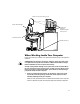
monitor screen at or below eye level wrists relaxed and flat monitor and keyboard positioned directly in front of user arms at desk level feet flat on the floor :KHQ :RUNLQJ ,QVLGH
7XUQ RII \RXU FRPSXWHU DQG DQ\ SHULSKHUDOV 'LVFRQQHFW \RXU FRPSXWHU DQG SHULSKHUDOV IURP WKHLU SRZHU VRXUFHV $OVR GLVFRQQHFW DQ\ WHOHSKRQH RU WHOHFRPPXQLFDWLRQ OLQHV IURP WKH FRPSXWHU Doing so reduces the potential for personal injury or shock. In addition, take note of these safety guidelines when appropriate: When you disconnect a cable, pull on its connector or on its strain-relief loop, not on the cable itself.
Handle all sensitive components in a static-safe area. If possible, use antistatic floor pads and workbench pads.
x
3UHIDFH $ERXW 7KLV *XLGH This guide is intended for anyone who uses a Dell OptiPlex GX1 or GX1p midsize Managed PC system. It can be used by both first-time and experienced computer users who want to learn about the features and operation of the systems or who want to upgrade their computers.
Appendix D, “Warranties and Return Policy,” describes the warranty for your Dell system and the “Total Satisfaction” Return Policy. :DUUDQW\ DQG 5HWXUQ 3ROLF\ ,QIRUPDWLRQ Dell Computer Corporation (“Dell”) manufactures its hardware products from parts and components that are new or equivalent to new in accordance with industrystandard practices. For information about the Dell warranty for your system, see Appendix D, “Warranties and Return Policy.
1RWDWLRQDO &RQYHQWLRQV The following subsections describe notational conventions used in this document. :DUQLQJV &DXWLRQV 1RWHV Throughout this guide, there may be blocks of text printed in bold type or in italic type.
Command lines consist of a command and may include one or more of the command’s possible parameters. Command lines are presented in the Courier New font. Example: del c:\myfile.doc Screen text is text that appears on the screen of your monitor or display. It can be a system message, for example, or it can be text that you are instructed to type as part of a command (referred to as a command line). Screen text is presented in the Courier New font.
&RQWHQWV &KDSWHU ,QWURGXFWLRQ System Features . . . . . . . . . . . . . . . . . . . . . . . . . . . . . . . . . . . . . . . . . . . . . . . . . . . 1-1 Hardware Features. . . . . . . . . . . . . . . . . . . . . . . . . . . . . . . . . . . . . . . . . . . . . . 1-2 Software Features . . . . . . . . . . . . . . . . . . . . . . . . . . . . . . . . . . . . . . . . . . . . . . 1-4 Manageability Features . . . . . . . . . . . . . . . . . .
System Setup Options . . . . . . . . . . . . . . . . . . . . . . . . . . . . . . . . . . . . . . . . . . . . . . 2-4 Time . . . . . . . . . . . . . . . . . . . . . . . . . . . . . . . . . . . . . . . . . . . . . . . . . . . . . . . . . 2-5 Date . . . . . . . . . . . . . . . . . . . . . . . . . . . . . . . . . . . . . . . . . . . . . . . . . . . . . . . . 2-5 Diskette Drive A and Diskette Drive B. . . . . . . . . . . . . . . . . . . . . . . . . . . . . . . 2-5 Drives: Primary and Secondary . . . . . . . . .
Using the Setup Password Feature. . . . . . . . . . . . . . . . . . . . . . . . . . . . . . . . . . . . Assigning a Setup Password . . . . . . . . . . . . . . . . . . . . . . . . . . . . . . . . . . . . . Operating With a Setup Password Enabled . . . . . . . . . . . . . . . . . . . . . . . . . . Deleting or Changing an Existing Setup Password . . . . . . . . . . . . . . . . . . . . Disabling a Forgotten Password . . . . . . . . . . . . . . . . . . . . . . . . . . . . . . . . . . . . . .
&KDSWHU :RUNLQJ ,QVLGH
$SSHQGL[ $ 7HFKQLFDO 6SHFLILFDWLRQV $ $SSHQGL[ % ,6$ &RQILJXUDWLRQ 8WLOLW\ 0HVVDJHV % ICU Error Messages . . . . . . . . . . . . . . . . . . . . . . . . . . . . . . . . . . . . . . . . . . . . . . . B-1 Configuration Manager Messages . . . . . . . . . . . . . . . . . . . . . . . . . . . . . . . . . . . . . B-6 $SSHQGL[ & 5HJXODWRU\ 1RWLFHV & FCC Notices (U.S. Only) .
)LJXUHV Figure 1-1. Figure 1-2. Figure 1-3. Figure 1-4. Figure 2-1. Figure 2-2. Figure 3-1. Figure 3-2. Figure 3-3. Figure 3-4. Figure 3-5. Figure 3-6. Figure 3-7. Figure 3-8. Figure 3-9. Figure 3-10. Figure 3-11. Figure 4-1. Figure 5-1. Figure 5-2. Figure 5-3. Figure 5-4. Figure 5-5. Figure 5-6. Figure 5-7. Figure 5-8. Figure 6-1. Figure 6-2. Figure 6-3. Figure 6-4. Figure 6-5. Figure 6-6. Figure 6-7. Figure 6-8. Figure 6-9. Figure 6-10. Figure 6-11. Figure 7-1. Figure 7-2. Figure 7-3. Figure 7-4.
7DEOHV Figure 7-6. Figure 7-7. Figure 7-8. Figure 7-9. Figure 7-10. Figure 7-11. Figure 7-12. Figure 7-13. Figure C-1. Figure C-2. Figure C-3. Figure C-4. Removing a Drive. . . . . . . . . . . . . . . . . . . . . . . . . . . . . . . . . . . . . . . . 7-6 Attaching the Bracket to the New Drive . . . . . . . . . . . . . . . . . . . . . . 7-6 Inserting the New Drive Into the Drive Bay . . . . . . . . . . . . . . . . . . . . 7-7 Attaching Diskette/Tape Drive and DC Power Cables . . . . . . . . . . . .
xxii
&+$37(5 ,QWURGXFWLRQ Dell® OptiPlex ® GX1 and GX1p midsize Managed PC systems are high-speed, expandable personal computers designed around the Intel® Pentium ® II microprocessor. Each computer system uses a high-performance Peripheral Component Interconnect (PCI) design that allows you to configure the computer system to your initial requirements and then add Dell-supported upgrades as necessary. These systems also support the Industry-Standard Architecture (ISA) bus for older expansion devices.
A secondary cache of 512 KB of static random-access memory (SRAM) included within the single-edge contact (SEC) cartridge, which also contains the microprocessor. System memory that can be increased up to 384 megabytes (MB) by installing 64- or 128-MB synchronous dynamic random-access memory (SDRAM) dual inline memory modules (DIMMs) in the three DIMM sockets on the system board. The system also supports both error checking and correction (ECC) and nonparity DIMMs.
A 64-bit accelerated graphics port (AGP) video subsystem, which includes the ATI 3D Rage Pro super video graphics array (SVGA) video controller. On the Dell OptiPlex GX1, this video subsystem contains 4 MB (upgradable to 8 MB) of synchronous graphics random-access memory (SGRAM) video memory; the Dell OptiPlex GX1p comes with 8 MB of SGRAM video memory. Maximum resolutions are 1600 x 1200 with 65,536 colors noninterlaced and 1280 x 1024 and 1024 x 768 with true-colors noninterlaced.
A Personal System/2 (PS/2)-style keyboard port and a PS/2-compatible mouse port. An optional integrated, 10/100-megabit-per-second (Mbps) 3Com® PCI 3C905B-TX Ethernet network interface controller (NIC). The NIC is configured using software described in Chapter 4, “Using Integrated Devices.” A 16-bit, integrated Plug and Play Crystal CS4236B audio controller that provides all the sound functions of the Sound Blaster Pro expansion card. For information, see your online System User’s Guide.
Dell Diagnostics for evaluating the computer’s components and devices. For information on using the diagnostics, see the chapter titled “Running the Dell Diagnostics” in the Diagnostics and Troubleshooting Guide. Network device drivers for several network operating systems. These drivers are described in Chapter 4, “Using Integrated Devices.” Desktop Management Interface (DMI) support, which enables the management of your computer system’s software and hardware.
configuration information and management information format (MIF) database values (see Figure 1-1). )LJXUH 'HOO 2SHQ0DQDJH 3URJUDP On systems running Windows 95, WIndows 98, and Windows NT 4.0, the Dell OpenManage program is available in client and administrator versions. The Dell OpenManage administrator version enables system administrators to view, manage, and inventory remote systems in a Dell DMI client network and incorporates the following manageability features, which are based on the DMI 2.
A System Properties window that enables network administrators to view, set, or disable certain hardware configuration settings for the local and remote systems in a Dell DMI network. Support for the Microsoft System Management Server (SMS), which allows the exporting of one or more groups to an SMS directory that the SMS administrator can access. A Monitor component for systems running Windows 95 and having a display data channel (DDC)-compliant video subsystem and monitor.
Download and install applications software Update the operating system and applications as required For additional information about the Intel LCM, refer to the documentation that accompanied the software. :DNHXS 2Q /$1 The Wakeup On LAN feature allows you to remotely turn on a Managed PC system that is in a sleep state.
6HFXULW\ &DEOH 6ORW DQG 3DGORFN 5LQJ On the back of the computer are a security cable slot and padlock ring (see Figure 1-2) for attaching commercially available antitheft devices. Security cables for personal computers usually include a segment of galvanized cable with an attached locking device and key.
8VLQJ WKH 3RZHU 6ZLWFK If the system does not turn off when the power switch is pressed, the system may be hung. Press and hold the power switch until the system turns off completely (this process may take several seconds). Alternatively, press the reset button to reset the system and reboot.
captive screw securing button locator pin )LJXUH $WWDFKLQJ WKH 2SWLRQDO 6WDQG IRU 9HUWLFDO 2ULHQWDWLRQ As you lower the stand into place, make sure that the locator pin (see Figure 1-3) fits into the corner hole of the hole pattern as shown. When the stand is in place, tighten the thumbscrew.
may increase the system’s power consumption beyond the limits set by the EPA’s ENERGY STAR® Computers program. ® )LJXUH (1(5*< 67$5 (PEOHP The EPA’s ENERGY STAR® Computers program is a joint effort between the EPA and computer manufacturers to reduce air pollution by promoting energy-efficient computer products. The EPA estimates that use of ENERGY STAR® computer products can save computer users up to two billion dollars annually in electricity costs.
NOTE: If you are a system administrator of corporate networks and you must download Windows 95 from a server to client systems, make sure that you have the Windows 95 backup media for the OptiPlex GX1 system on your server before downloading. ,QWHO 3,,; ,1) 8SGDWH ,QVWDOOHU IRU :LQGRZV NOTE: The following procedure applies only to versions of Windows 95 installed by Dell.
&OLFN 1H[W WR FRQWLQXH The system finds the hardware device driver on the hard-disk drive and installs it. &OLFN )LQLVK WR FRQWLQXH The system continues its start-up routine. When Windows 95 finishes loading, a dialog box appears and informs you that the system configuration settings have changed and asks if you want to restart your system. &OLFN 2.
&+$37(5 8VLQJ WKH 6\VWHP 6HWXS 3URJUDP Each time you turn on your computer system or press the reset button, the system compares the hardware installed in the system to the hardware listed in the system configuration information stored in nonvolatile random-access memory (NVRAM) on the system board. If the system detects a discrepancy, it generates error messages that identify the incorrect configuration settings. The system then prompts you to enter the System Setup program to correct the setting.
3UHVV ) ! LPPHGLDWHO\ ZKHQ WKH F2 = Setup SURPSW DSSHDUV LQ WKH XSSHU ULJKW FRUQHU RI WKH 'HOO ORJR VFUHHQ If you wait too long and your operating system begins to load into memory, let the system complete the load operation; then shut down the system and try again. NOTE: To ensure an orderly system shutdown, consult the documentation that accompanied your operating system. You can also enter the System Setup program by responding to certain error messages.
8VLQJ WKH 6\VWHP 6HWXS 3URJUDP Table 2-1 lists the keys you use to view or change information on the System Setup screens and to exit the program. 7DEOH 6\VWHP 6HWXS 1DYLJDWLRQ .H\V .H\V $FWLRQ or Moves to the next field. Moves to the previous field. or or or Cycles through the options in a field. In many fields, you can also type the appropriate value. Scrolls through help information. Switches between Page 1 and Page 2.
Page 1 of 2 help title box configuration options Dell Computer Corporation (www.dell.com) BIOS Version: XXX System OptiPlex GX1 400M Setup 13:17:02 Date: Mon April 1, 1998 This category sets the time in 24-hour format (hours:minutes: Diskette Drive A: 3.5 inch, 1.44 MB seconds) for the internal clock/ Diskette Drive B: Not Installed calendar.
7LPH Time resets the time on the computer’s internal clock. Time is kept in a 24-hour format (hours:minutes:seconds). To change the time, press the right-arrow key to increase the number in the highlighted field or press the leftarrow key to decrease the number. If you prefer, you can type numbers in each of the appropriate fields. 'DWH Date resets the date on the computer’s internal calendar.
“IDE2”). It is recommended that you use the secondary EIDE interface connector for EIDE CD-ROM and EIDE tape drives. NOTES: For all devices from Dell that use the built-in EIDE controller, set the appropriate Drive option to Auto. For small computer system interface (SCSI) devices, set the appropriate Drive option to None. You must have an EIDE device connected to the primary EIDE interface if you have an EIDE device connected to the secondary EIDE interface.
card (the base memory below the 15-MB address comes from the dual in-line memory modules [DIMMs] on the system board). The Reserved Memory option has the following options: None (the default option) 512K - 640K 15M - 16M &38 6SHHG CPU Speed indicates the processor speed at which your system boots.
'$& 6QRRS DAC Snoop lets you correct video problems that may occur when certain video add-in cards are used. The default is Off. If you are using a video add-in card and problems such as incorrect colors or blank windows occur, set DAC Snoop to On. $&3, This option controls the operation of the system’s Advanced Configuration and Power Interface (ACPI) feature. When ACPI is set to On, momentarily pressing the power button places the system in a power-saving mode.
3DVVZRUG 6WDWXV When Setup Password is set to Enabled, Password Status allows you to prevent the system password from being changed or disabled at system start-up. To lock the system password, you must first assign a setup password in the Setup Password option and then change the Password Status option to Locked. In this state, the system password cannot be changed through the System Password option and cannot be disabled at system start-up by pressing .
attempts to boot from these devices. To view the Device List screen, press and the right-arrow key. Table 2-2 lists other navigation keys used on the Device List screen. 7DEOH 'HYLFH /LVW 6FUHHQ 1DYLJDWLRQ .H\V .
NOTE: Non-Plug and Play devices appear in this list as Adapters without ID support. When determining the order of devices to boot from, the system first considers the order of the devices listed under the Device Controller Priority option, then the order of devices under Boot Device Priority.
6HWXS 3DVVZRUG Setup Password lets you restrict access to your computer’s System Setup program in the same way that you restrict access to your system with the system password feature. The options are: Not Enabled (the default option) Enabled Disabled by Jumper NOTE: Read “Using the Setup Password Feature” found later in this chapter for instructions on assigning a setup password and using or changing an existing setup password.
NOTE: The power management feature monitors activity of a mouse connected to the Personal System/2 (PS/2)-compatible mouse port. By setting Power Management to Maximum, Regular, or Minimum, you can set predefined time-out periods (see Table 2-3) for the two successive monitor shutdown stages, standby and off. NOTE: Each monitor manufacturer defines the details of the shutdown stages for its own monitors.
7DEOH 3RZHU 7LPH 2XW 3HULRGV 3RZHU 0DQDJHPHQW 6HWWLQJ (,'( 'ULYH 6SLQGRZQ 7LPH 2XWV 0RQLWRU 6WDQGE\ 7LPH 2XWV 0RQLWRU 2II 7LPH 2XWV Disabled Never Never Never Maximum 20 minutes 10 minutes 1 hour Regular 20 minutes 20 minutes 1 hour Minimum 20 minutes 1 hour Never :DNHXS 2Q /$1 Wakeup On LAN determines whether the Wakeup On LAN feature is set to On or Off. You must reboot your system before a change takes effect.
NOTES: When two COM ports share an IRQ setting, you can use either port as necessary, but you may not be able to use them both at the same time. If the second port (COM3 or COM4) is also in use, the built-in port is turned off. If you are using the Microsoft Windows 95 or IBM OS/2 operating system, you cannot use both serial ports at the same time.
With Auto (the default option) selected, the system turns off the built-in diskette drive controller when necessary to accommodate a controller card installed in an expansion slot. With Write Protect selected, nothing can be written to diskette drives and tape drives using the system’s built-in diskette drive controller. (The system can still read from the drives.
Your Dell system is shipped to you without the system password feature enabled. If system security is a concern, you should operate your system only with system password protection. You can assign a system password, as described in the next subsection, “Assigning a System Password,” whenever you use the System Setup program. After a system password is assigned, only those who know the password have full use of the system.
As you press each character key (or the spacebar for a blank space), a placeholder appears in the field. The password assignment operation recognizes keys by their location on the keyboard, without distinguishing between lowercase and uppercase characters. For example, if you have an M in your password, the system recognizes either M or m as correct. Certain key combinations are not valid. If you enter one of these combinations, the speaker emits a beep.
If a wrong or incomplete system password is entered, the following message appears on the screen: ** Incorrect password. ** Enter password: If an incorrect or incomplete system password is entered again, the same message appears on the screen. The third and subsequent times an incorrect or incomplete system password is entered, the system displays the following message: ** Incorrect password. ** Number of unsuccessful password attempts: 3 System halted! Must power down.
7R DVVLJQ D QHZ SDVVZRUG IROORZ WKH SURFHGXUH LQ ´$VVLJQLQJ D 6\VWHP 3DVVZRUGµ IRXQG HDUOLHU LQ WKLV VHFWLRQ 8VLQJ WKH 6HWXS 3DVVZRUG )HDWXUH Your Dell system is shipped to you without the setup password feature enabled. If system security is a concern, you should operate your system with setup password protection. You can assign a setup password, as described in the next subsection, “Assigning a Setup Password,” whenever you use the System Setup program.
If you do not enter the correct password in three tries, the system lets you view, but not modify, the System Setup screens—with the following exceptions: You can still modify the Date, Time, CPU Speed, Num Lock, and Speaker options. If System Password is not enabled and is not locked via the Password Status option, you can assign a system password (however, you cannot disable or change an existing system password).
5HFRQQHFW \RXU FRPSXWHU DQG SHULSKHUDOV WR WKHLU SRZHU VRXUFHV DQG WKHQ WXUQ WKHP RQ Booting your system with the PSWD jumper plug removed erases the existing password(s). (QWHU WKH 6\VWHP 6HWXS SURJUDP DQG YHULI\ WKDW WKH SDVVZRUG LV GLV DEOHG 3URFHHG WR VWHS LI \RX ZDQW WR DVVLJQ D QHZ SDVVZRUG NOTE: Before you assign a new system and/or setup password, you must replace the PSWD jumper plug.
&+$37(5 8VLQJ WKH ,6$ &RQILJXUDWLRQ 8WLOLW\ The ISA Configuration Utility (ICU) is used by the system to track what expansion cards are installed and what resources are used. With this information, the system automatically configures Plug and Play expansion cards and Peripheral Component Interconnect (PCI) expansion cards and can tell you how to configure non-Plug and Play Industry-Standard Architecture (ISA) expansion cards manually by setting jumpers or switches.
4XLFN 6WDUW To quickly get started using this utility, follow these steps: 'HWHUPLQH ZKHWKHU \RX QHHG WR UXQ WKH ,&8 See “When to Run the ICU” found later in this chapter for detailed instructions. 3HUIRUP DQ\ UHTXLUHG SUHSDUDWRU\ VWHSV EHIRUH VWDUWLQJ WKH XWLOLW\ Preparatory steps include making a program diskette, copying your mouse driver to this diskette, and making a backup copy of this diskette. See “Preparing to Use the ICU” found later in this chapter for detailed instructions.
$ERXW WKH ,&8 Before your system was shipped from Dell, a technician used the ICU to enter the correct information for the expansion cards initially installed in your computer. If your system was shipped with Dell-installed software, the ICU diskette image (from which you can make an ICU diskette) is installed on your hard-disk drive. (Your system may also be accompanied by an ISA Configuration Utility Diskette.
After you have run the ICU for your non-Plug and Play ISA expansion cards and it has configured all your Plug and Play and PCI expansion cards, you can use the utility to lock the configuration of your Plug and Play and PCI expansion cards so that they are always assigned the same resources. See your online System User’s Guide or “Locking and Unlocking Cards” found later in this chapter for details.
6WDUWLQJ WKH ,&8 After you have completed the procedures in “Preparing to Use the ICU” found earlier in this chapter, insert the backup copy of the ICU diskette into drive A. Then either turn on your system or reboot it by pressing the reset button. $FFHVVLQJ +HOS You can access online help in the ICU in four ways: Select Contents from the Help menu to display a list of topics. Select a topic and click Help. Help text on that topic appears in a dialog box.
7DEOH ,&8 .H\V .H\ V $FWLRQ Displays the menu containing the underlined letter x and performs the operation indicated by the menu item containing the underlined letter y. For example, to save a file (that is, to display the File menu and select the Save menu option), press and . Moves from one control button or list to another. Up- and downarrow keys Moves up and down through items in a list. Spacebar Highlights an item in a list.
,I \RX ZDQW WKH ,&8 WR VHOHFW WKH UHVRXUFHV IRU WKH FDUG FOLFN 2. 2WKHU ZLVH VNLS WR VWHS The ICU uses the default resources set by the card manufacturer whenever possible. If the ICU cannot find a resource that is valid for the card and available in the system, the utility generates an error message. See Appendix B, “ISA Configuration Utility Messages,” for an explanation of the message and a possible solution to the conflict.
7R FKDQJH WKH UHVRXUFH VHWWLQJV FOLFN WKH GRZQ DUURZ QH[W WR WKH &RQ ILJXUDWLRQ &KRLFH ER[ 7KHQ FOLFN WKH QHZ UHVRXUFH VHWWLQJ IURP WKH OLVW RI DYDLODEOH VHWWLQJV VHH )LJXUH You cannot manually enter a value; you must choose a setting from the list. If there is only one setting listed, no other settings are available. The setting that you select may affect the resources available.
made to the resource values are overwritten by the default values for the new configuration choice. &OLFN 2. LQ WKH &RQILJXUDWLRQ 6HWWLQJV GLDORJ ER[ ZKHQ \RX KDYH ILQ LVKHG VHOHFWLQJ UHVRXUFHV IRU WKH IXQFWLRQ NOTE: After modifying the system configuration, you must turn off the system to install, remove, or change jumper settings on the non-Plug and Play ISA expansion cards to match the settings you selected in the ICU.
)LJXUH 6SHFLI\ ,QWHUUXSW 'LDORJ %R[ If you are providing a value for the interrupt request (IRQ) or direct memory access (DMA) resource, click the down arrow beneath Available Resources. A smaller Specify list box appears (see Figure 3-8). Click the value you want to assign to the resource. Then click OK.
:KHQ \RX KDYH ILQLVKHG VHOHFWLQJ UHVRXUFHV IRU WKH XQOLVWHG FDUG FOLFN 2. LQ WKH &RQILJXUH 8QOLVWHG &DUG GLDORJ ER[ A message box appears, notifying you either that the card is using its default settings or that it cannot use its default settings and must be reconfigured. &OLFN 2.
NOTE: When you modify an unlisted card, the ICU cannot show you the valid resources for the card. Therefore, you must have documentation from the card manufacturer that describes the resources and resource settings that the card can use. )ROORZ VWHSV WKURXJK LQ ´$GGLQJ D /LVWHG &DUGµ IRXQG HDUOLHU LQ WKLV FKDSWHU 7KHQ FRQWLQXH ZLWK VWHS RI WKLV SURFHGXUH &OLFN 2. WR FRPSOHWH WKH FDUG PRGLILFDWLRQV DQG UHWXUQ WR WKH ,&8 ZLQGRZ You have completed this procedure; do not proceed to step 5.
NOTE: After modifying the system configuration, you must turn off the system to install, remove, or change jumper settings on the non-Plug and Play ISA expansion cards to match the settings you selected in the ICU. 5HPRYLQJ D &DUG Before you remove a non-Plug and Play ISA expansion card from your computer, you must use the ICU to remove the card from the system configuration. NOTE: When you remove a Plug and Play or PCI expansion card from your computer, you do not need to run the ICU.
)LJXUH 6\VWHP 5HVRXUFH 8VDJH 'LDORJ %R[ To determine which card uses a particular resource shown in the System Resource Usage dialog box, select the resource in question and then click Used By Card. The Card Resource Usage dialog box appears with the information. To view the resources that a particular card is using, select the card from the list displayed in the ICU window, and then select Card Resources from the View menu or click View.
If you click Yes, the ICU saves the updated system configuration information into NVRAM. If you click No, you exit the ICU without saving any of your configuration changes. If you click Cancel, nothing is saved and the utility continues to operate. /RFNLQJ DQG 8QORFNLQJ &DUGV The ICU includes a locking mechanism that enables you to allocate the system resources for all or for some functions of Plug and Play and PCI expansion cards.
/RFNLQJ DQG 8QORFNLQJ &RQILJXUDWLRQ 5HVRXUFHV You can also lock and unlock individual resources for a Plug and Play or PCI expansion card. To do so, perform the following steps: ,I LW LV QRW DOUHDG\ LQVWDOOHG LQVWDOO WKH 3OXJ DQG 3OD\ RU 3&, H[SDQVLRQ FDUG 7KHQ WXUQ RQ WKH V\VWHP Complete steps 2 through 9 in “Installing an Expansion Card” in Chapter 6. 6WDUW WKH ,&8 See “Starting the ICU” found earlier in this chapter.
&+$37(5 8VLQJ ,QWHJUDWHG 'HYLFHV This chapter describes the configuration software provided with your system for the following integrated devices: Video controller Audio controller Optional network interface controller (NIC) See the corresponding section in this chapter for the device you want to configure or reconfigure. 9LGHR &RQWUROOHU Your system has an ATI 3D Rage Pro (2X) accelerated graphics port (AGP) video controller.
programs for the drivers and utilities needed by your system. To access the Program Diskette Maker, click the Start button and point to Programs. Then point to Dell Accessories and click Program Disk Maker. If your computer is part of a centrally managed network, check with your network administrator for information on reinstalling drivers and utilities.
$XGLR &RQWUROOHU Your system has a Crystal CS4236B audio controller. If your system came with a Dellinstalled operating system, the audio drivers for that operating system are installed on your hard-disk drive. For information on reinstalling audio drivers, reconfiguring the audio controller, or using the audio utilities provided with your system, see “Using the Audio Controller” in your online System User’s Guide.
1HWZRUN &DEOH 5HTXLUHPHQWV Your computer’s NIC connector (an RJ45 connector located on the back panel) is designed for attaching an unshielded twisted pair (UTP) Ethernet cable. Press one end of the UTP cable into the NIC connector until the cable snaps securely into place. Connect the other end of the cable to an RJ45 jack wall plate or to an RJ45 port on a UTP concentrator or hub, depending on your network configuration. Observe the following cabling restrictions for 10BASE-T and 100BASE-TX networks.
&RQILJXULQJ WKH 1,& This subsection provides instructions for configuring or reconfiguring the computer’s integrated NIC under the following operating systems: Microsoft Windows NT Microsoft Windows 95 or Windows 98 Microsoft Windows for Workgroups™ MS-DOS® NOTE: The NIC drivers for systems running a Dell-installed Windows NT 4.0 or Windows 95 operating system are automatically detected and installed. Instructions for reconfiguring the NIC driver are included in the following subsections.
&OLFN +DYH 'LVN ,QVHUW GLVNHWWH LQWR GULYH $ W\SH a:\ DQG WKHQ FOLFN 2. 6HOHFW &RP )DVW (WKHU/LQN (WKHU/LQN ;/ 3&, %XV 0DVWHU 1,& & % 7; DQG WKHQ FOLFN 2. :KHQ SURPSWHG IRU GLVNHWWH FOLFN 2.
&OLFN
6WDUW :LQGRZV &OLFN WKH 6WDUW EXWWRQ SRLQW WR 6HWWLQJV DQG FOLFN &RQWURO 3DQHO 7KHQ GRXEOH FOLFN WKH 6\VWHP LFRQ ,Q WKH 6\VWHP 3URSHUWLHV ZLQGRZ FOLFN WKH 'HYLFH 0DQDJHU WDE ,Q WKH OLVW RI V\VWHP GHYLFHV GRXEOH FOLFN 2WKHU 'HYLFHV 7KHQ FOLFN 3&, (WKHUQHW &RQWUROOHU &OLFN 3URSHUWLHV WR DFFHVV WKH 3&, (WKHUQHW &RQWUROOHU ZLQGRZ &OLFN WKH 'ULYHU WDE DQG WKHQ FOLFN 8SGDWH 'ULYHU The Update Device Driver Wizard starts.
&RQQHFW WKH QHWZRUN FDEOH WR WKH EDFN RI \RXU FRPSXWHU See “Network Cable Requirements” found earlier in this section for more information. 9HULI\ WKDW WKH 1,& LV HQDEOHG LQ WKH 6\VWHP 6HWXS SURJUDP See Chapter 2, “Using the System Setup Program,” for more information.
06 '26 1,& To connect your system to, and configure it for use on, an Ethernet network, you must complete the following steps: 8VH WKH 3URJUDP 'LVNHWWH 0DNHU ORFDWHG LQ WKH 'HOO $FFHVVRULHV SUR JUDP JURXS RU IROGHU WR PDNH D GLVNHWWH FRS\ RI WKH 1,& GULYHUV LQVWDOOHG RQ \RXU KDUG GLVN GULYH &RQQHFW WKH QHWZRUN FDEOH WR WKH EDFN RI \RXU FRPSXWHU See “Network Cable Requirements” found earlier in this section for more information.
&+$37(5 :RUNLQJ ,QVLGH
7XUQ RII \RXU FRPSXWHU DQG DOO SHULSKHUDOV 'LVFRQQHFW \RXU FRPSXWHU DQG SHULSKHUDOV IURP WKHLU $& SRZHU VRXUFHV $OVR GLVFRQQHFW DQ\ WHOHSKRQH RU WHOHFRPPXQLFDWLRQ OLQHV IURP WKH FRPSXWHU 'RLQJ VR UHGXFHV WKH SRWHQWLDO IRU SHUVRQDO LQMXU\ RU VKRFN ,I \RX DUH GLVFRQQHFWLQJ D SHULSKHUDO IURP WKH FRPSXWHU RU DUH UHPRY LQJ D FRPSRQHQW IURP WKH V\VWHP ERDUG ZDLW VHFRQGV DIWHU WXUQLQJ RII WKH FRPSXWHU EHIRUH GLVFRQQHFWLQJ WKH SHULSKHUDO RU UHPRYLQJ WKH FRPSRQHQW WR DYRLG SRVVLEOH GDPDJ
)LJXUH 3DGORFN ,QVWDOOHG 5HPRYH WKH RSWLRQDO VWDQG LI RQH LV DWWDFKHG See “Using the Optional Stand for Vertical Orientation” in Chapter 1 for instructions. &$87,21 6HH ´3URWHFWLQJ $JDLQVW (OHFWURVWDWLF 'LVFKDUJHµ LQ WKH VDIHW\ LQVWUXFWLRQV DW WKH IURQW RI WKLV JXLGH 5HPRYH WKH FRYHU From the front of the computer, press in the two securing buttons (located on the sides of the cover toward the back).
securing buttons (2) front of computer )LJXUH 5HPRYLQJ WKH &RPSXWHU &RYHU 5HSODFLQJ WKH &RPSXWHU &RYHU Use the following procedure to replace the computer cover: &KHFN DOO FDEOH FRQQHFWLRQV HVSHFLDOO\ WKRVH WKDW PLJKW KDYH FRPH ORRVH GXULQJ \RXU ZRUN )ROG FDEOHV RXW RI WKH ZD\ VR WKDW WKH\ GR QRW FDWFK RQ WKH FRPSXWHU FRYHU 0DNH VXUH FDEOHV DUH QRW URXWHG RYHU WKH GULYH FDJH³WKH\ ZLOO SUHYHQW WKH FRYHU IURP FORVLQJ SURSHUO\ &KHFN WR VHH WKDW QR WRROV RU H[WUD SDUWV LQFOXGLQJ VFUHZV
ledge hooks in slots (4) )LJXUH 5HSODFLQJ WKH &RPSXWHU &RYHU ,I \RX DUH XVLQJ WKH RSWLRQDO VWDQG UHDWWDFK LW See “Using the Optional Stand for Vertical Orientation” in Chapter 1 for instructions. ,I \RX DUH XVLQJ D SDGORFN WR VHFXUH \RXU V\VWHP UHLQVWDOO WKH SDGORFN ,QVLGH
back of computer power supply expansioncard cage system board left side internal drive bracket right side drive cage front of computer )LJXUH &RPSXWHU 2ULHQWDWLRQ 9LHZ Figure 5-5 shows your computer with its cover removed. Refer to this illustration to locate interior features and components discussed in this guide. When you look inside your computer, note the direct current (DC) power cables coming from the power supply.
To change a jumper setting, pull the plug off its pin(s) and carefully fit it down onto the pin(s) indicated. &$87,21 0DNH VXUH \RXU V\VWHP LV WXUQHG RII EHIRUH \RX FKDQJH D MXPSHU VHWWLQJ 2WKHUZLVH GDPDJH WR \RXU V\VWHP RU XQSUHGLFWDEOH UHVXOWV PD\ RFFXU A jumper is referred to as open or unjumpered when the plug is pushed down over only one pin or if there is no plug at all. When the plug is pushed down over two pins, the jumper is referred to as jumpered .
DC power cable drive interface cable power supply AC power receptacle padlock ring parallel port connector chassis intrusion switch serial port 1 connector mouse connector keyboard connector USB connectors (2) security cable slot serial port 2 connector video connector line-in jack optional integrated NIC connector microphone jack line-out jack )LJXUH ,QVLGH WKH &KDVVLV 5-8 Dell OptiPlex GX1 and GX1p Midsize Managed PC Systems Reference and
jumpered unjumpered )LJXUH 6\VWHP %RDUG -XPSHUV Working Inside Your Computer 5-9
7DEOH 6\VWHP %RDUG -XPSHU 6HWWLQJV -XPSHU 6HWWLQJ PSWD (default) 'HVFULSWLRQ Password features are enabled. Password features are disabled. BIOS (default) Reserved (do not change). BUS66M Reserved (do not change). 266MHZ* Jumpered when the microprocessor’s internal speed is 266 MHz. 300MHZ* Jumpered when the microprocessor’s internal speed is 300 MHz. 333MHZ* Jumpered when the microprocessor’s internal speed is 333 MHz.
6\VWHP %RDUG DQG 5LVHU %RDUG /DEHOV Table 5-2 lists the labels for connectors and sockets on your system board and riser board, and it gives a brief description of their functions.
7DEOH 6\VWHP %RDUG DQG 5LVHU %RDUG &RQQHFWRUV DQG 6RFNHWV FRQWLQXHG &RQQHFWRU RU 6RFNHW 'HVFULSWLRQ POWER_1 Main power input connector POWER_2 3.
slots (2) securing lever left side of computer tabs (2) )LJXUH 5HPRYLQJ WKH ([SDQVLRQ &DUG &DJH 6OLGH WKH H[SDQVLRQ FDUG FDJH RXW RI WKH FKDVVLV /LIW WKH H[SDQVLRQ FDUG FDJH XS DQG DZD\ IURP WKH FKDVVLV 5HSODFLQJ WKH ([SDQVLRQ &DUG &DJH Use the following procedure to replace the expansion-card cage: :LWK WKH VHFXULQJ OHYHU LQ WKH XSULJKW SRVLWLRQ DOLJQ WKH VORWV LQ WKH OHIW VLGH RI WKH H[SDQVLRQ FDUG FDJH ZLWK WKH WDEV RQ WKH OHIW VLGH RI WKH FKDVVLV VHH )LJXUH 5RWD
5RWDWLQJ WKH 3RZHU 6XSSO\ $ZD\ )URP WKH 6\VWHP %RDUG To access some components on the system board, you may have to rotate the system power supply out of the way.
&+$37(5 ,QVWDOOLQJ 6\VWHP %RDUG 2SWLRQV This chapter describes how to install the following options: Industry-Standard Architecture (ISA) and Peripheral Component Interconnect (PCI) expansion cards System memory Video memory Microprocessor This chapter also includes instructions for replacing the system battery, if necessary. Use Figure 6-1 to locate the system board features.
DIMM sockets (3) telephony (DIMM_A–DIMM_C) connector (TAPI) parallel/serial port 1 connectors (stacked) (PARALLEL/SERIAL1) 3.
8-bit ISA expansion card 16-bit ISA expansion card 32-bit PCI expansion card )LJXUH ([SDQVLRQ &DUGV ([SDQVLRQ 6ORWV Expansion cards are installed on the computer’s riser board (see Figure 6-3). The riser board plugs into the RISER connector on the system board (see Figure 6-1) and is considered an extension of the system board. The system accommodates a mix of 32-bit PCI expansion cards and 8- and 16-bit ISA expansion cards. (See Figure 6-2 for examples of ISA and PCI expansion cards.
LED PCI5 ISA2 PCI4 ISA1 PCI3 HDLED connector P1 PCI2 PCI1 )LJXUH 5LVHU %RDUG ([SDQVLRQ &DUG &RQQHFWRUV ,QVWDOOLQJ DQ ([SDQVLRQ &DUG Follow this procedure to install an expansion card: ,I \RX DUH LQVWDOOLQJ D QRQ 3OXJ DQG 3OD\ ,6$ H[SDQVLRQ FDUG HQWHU WKH ,6$ &RQILJXUDWLRQ 8WLOLW\ ,&8 DQG DGG WKH QHZ H[SDQVLRQ FDUG WR \RXU FRQILJXUDWLRQ See Chapter 3, “Using the ISA Configuration Utility,” for instructions.
filler bracket )LJXUH 5HPRYLQJ WKH )LOOHU %UDFNHW ,QVWDOO WKH H[SDQVLRQ FDUG Insert the card-edge connector firmly into the expansion-card connector on the riser board. Gently rock the card into the connector until the card is fully seated (see Figure 6-5).
,I \RX DUH LQVWDOOLQJ DQ RSWLRQDO :DNHXS 2Q /$1 QHWZRUN FDUG DWWDFK WKH WKUHH ZLUH SRZHU FDEOH WKDW FDPH ZLWK WKH FDUG WR WKH 3 FRQQHFWRU RQ WKH ULVHU ERDUG VHH )LJXUH DQG WR WKH QHWZRUN LQWHUIDFH FRQ WUROOHU 1,& FDUG 5HSODFH WKH H[SDQVLRQ FDUG FDJH LQ WKH FKDVVLV DV LQVWUXFWHG LQ ´5HSODFLQJ WKH ([SDQVLRQ &DUG &DJHµ LQ &KDSWHU &RQQHFW DQ\ FDEOHV WKDW VKRXOG EH DWWDFKHG WR WKH FDUG See the documentation that came with the card for information about its cable connections.
,I \RX DUH UHPRYLQJ WKH FDUG SHUPDQHQWO\ LQVWDOO D PHWDO ILOOHU EUDFNHW RYHU WKH HPSW\ FDUG VORW RSHQLQJ NOTE: Installing filler brackets over empty card-slot openings is necessary to maintain Federal Communications Commission (FCC) certification of the system. The brackets also keep dust and dirt out of your computer.
DIMMs (3) DIMM sockets )LJXUH ',00V DQG ',00 6RFNHWV Table 6-1 lists sample memory configurations and shows valid DIMM combinations and socket placements for each configuration. .
3HUIRUPLQJ D 0HPRU\ 8SJUDGH Follow this procedure to perform a memory upgrade: &$87,21 6HH ´3URWHFWLQJ $JDLQVW (OHFWURVWDWLF 'LVFKDUJHµ LQ WKH VDIHW\ LQVWUXFWLRQV DW WKH IURQW RI WKLV JXLGH 5HPRYH WKH FRPSXWHU FRYHU DFFRUGLQJ WR WKH LQVWUXFWLRQV LQ ´5HPRYLQJ WKH &RPSXWHU &RYHUµ LQ &KDSWHU 5RWDWH WKH SRZHU VXSSO\ RXW RI WKH ZD\ DFFRUGLQJ WR WKH LQVWUXFWLRQV LQ ´5RWDWLQJ WKH 3RZHU 6XSSO\ $ZD\ )URP WKH 6\VWHP %RDUGµ LQ &KDSWHU 'HWHUPLQH WKH ',00 VRFNHWV LQWR ZKLFK \RX ZLOO LQVWDOO ',0
3UHVV ) ! WR HQWHU WKH 6\VWHP 6HWXS SURJUDP FKHFN WKH 6\VWHP 0HPRU\ FDWHJRU\ LQ WKH ORZHU ULJKW FRUQHU RI 3DJH DQG UHVHW &KDVVLV ,QWUXVLRQ WR 1RW 'HWHFWHG The system should have already changed the value in the System Memory category to reflect the newly installed memory. Verify the new total.
securing clips (2) )LJXUH ,QVWDOOLQJ D ',00 5HPRYLQJ D ',00 To remove a DIMM, press the securing clips outward (see Figure 6-8) simultaneously until the DIMM disengages from the socket (it should pop up slightly). )LJXUH 5HPRYLQJ D ',00 $GGLQJ 9LGHR 0HPRU\ 2SWL3OH[ *; 2QO\ You can upgrade video memory on an OptiPlex GX1 from 4 to 8 MB by installing a video-memory upgrade module (OptiPlex GX1p systems come with 8 MB of video memory).
7R DFFHVV WKH YLGHR PHPRU\ XSJUDGH VRFNHW ODEHOHG ´ 9,'(2B83*5$'(µ RQ WKH V\VWHP ERDUG UHPRYH WKH H[SDQVLRQ FDUG FDJH DV GHVFULEHG LQ ´5HPRYLQJ WKH ([SDQVLRQ &DUG &DJHµ LQ &KDSWHU 2ULHQW WKH PRGXOH DV VKRZQ LQ )LJXUH 7KHQ LQVWDOO LW LQ WKH VRFNHW Video memory modules are keyed, or designed to fit in the socket in only one direction. The socket on the system board is notched so that the video memory module can be firmly seated only one way.
5XQ WKH 9LGHR 7HVW *URXS LQ WKH 'HOO 'LDJQRVWLFV WR WHVW WKH QHZ YLGHR PHPRU\ See your Diagnostics and Troubleshooting Guide for instructions on running the Dell Diagnostics and troubleshooting any problems that occur. 8SJUDGLQJ WKH 0LFURSURFHVVRU To take advantage of future options in speed and functionality, you can replace the microprocessor on your system board with any Dell-supported microprocessor upgrade.
SEC cartridge heat sink tabs (2) tabbed guide-bracket assembly connector )LJXUH 5HPRYLQJ WKH 0LFURSURFHVVRU ,QVHUW WKH QHZ 6(& FDUWULGJH KHDW VLQN DVVHPEO\ LQWR WKH V\VWHP ERDUG FRQQHFWRU Press the SEC release latches outward until they snap into position. Orient the assembly with the heat sink facing toward the right (as you face the front of the chassis), and press the SEC cartridge firmly into its connector until it is fully seated.
5RWDWH WKH SRZHU VXSSO\ EDFN LQWR SRVLWLRQ 5HSODFH WKH FRPSXWHU FRYHU UHFRQQHFW \RXU FRPSXWHU DQG SHULSKHUDOV WR WKHLU SRZHU VRXUFHV DQG WXUQ WKHP RQ NOTE: After you remove and replace the cover, the chassis intrusion detector will cause the following message to be displayed at the next system start-up: ALERT! Cover was previously removed.
AC power. In this case, you must enter the System Setup program and reset the configuration options.
BATTERY socket battery )LJXUH 6\VWHP %DWWHU\ DQG %DWWHU\ 6RFNHW 5HSODFH WKH H[SDQVLRQ FDUG FDJH DV GHVFULEHG LQ ´5HSODFLQJ WKH ([SDQVLRQ &DUG &DJHµ LQ &KDSWHU 5HSODFH WKH FRPSXWHU FRYHU UHFRQQHFW \RXU FRPSXWHU DQG SHULSKHUDOV WR WKHLU SRZHU VRXUFHV DQG WXUQ WKHP RQ NOTE: After you remove and replace the cover, the chassis intrusion detector will cause the following message to be displayed at the next system start-up: ALERT! Cover was previously removed.
6-18 Dell OptiPlex GX1 and GX1p Midsize Managed PC Systems Reference and Installation Guide
&+$37(5 ,QVWDOOLQJ 'ULYHV Your Dell computer has five drive bays for installing the following types of drives (see Figure 7-1): The externally accessible drive bays at the front of the computer consist of one 3.5-inch drive bay (dedicated to a 3.5-inch diskette drive) and two 5.25-inch bays that can hold up to two half-height, 5.25-inch devices—typically tape drives or CD-ROM drives. The two vertically positioned hard-disk drive bays can each hold a 3.
5HPRYLQJ DQG 5HSODFLQJ )URQW 3DQHO ,QVHUWV Empty drive bays contain a front-panel insert to protect the inside of the computer from dust particles and also to ensure proper airflow within the computer. Before you install a drive in an empty drive bay, you must first remove the front-panel insert. To remove the insert covering a 5.
To remove the insert covering the 3.5-inch bay, follow these steps: &RPSOHWH VWHSV DQG RI WKH SURFHGXUH IRU UHPRYLQJ D LQFK LQVHUW ,QVLGH WKH FRYHU ORFDWH WKH HMHFW EXWWRQ PHFKDQLVP IRU WKH LQFK ED\ VHH )LJXUH 3UHVV WKH PHFKDQLVP WRZDUG WKH IURQW SDQHO WR VQDS WKH SODVWLF LQVHUW RXW RI LWV RSHQLQJ computer cover (upside down) eject button mechanism )LJXUH 5HPRYLQJ WKH )URQW 3DQHO ,QVHUW IRU WKH ,QFK %D\ To replace the front-panel insert for the 3.
The drive’s interface connector is a card-edge connector or a header connector, as shown in Figure 7-5. card-edge connector on drive notch colored header connector strip on drive interface cables colored strip )LJXUH 'ULYH ,QWHUIDFH &RQQHFWRUV When attaching the interface cable to a drive, be sure to match the colored strip on the cable to pin 1 of the drive’s interface connector.
,QVWDOOLQJ D 'ULYH LQ D ,QFK 'ULYH %D\ The 5.
bracket tabs (2) )LJXUH 5HPRYLQJ D 'ULYH If a drive is already installed in the bay and you are replacing it, be sure to disconnect the DC power cable and interface cable from the back of the drive before sliding the bracket out of the bay. To remove the old drive from the bracket, turn the drive/bracket assembly upside down and unscrew the four screws that secure the drive to the bracket (see Figure 7-7).
To further ensure proper positioning of the drive in the chassis, insert and tighten all four screws in the order in which the holes are numbered (the holes are marked “1” through “4”). 6OLGH WKH QHZ GULYH LQWR WKH GULYH ED\ XQWLO LW VQDSV VHFXUHO\ LQWR SODFH VHH )LJXUH Make sure that both bracket tabs snap into place in the drive bay. 5.
DC power cable diskette/tape drive interface cable power input connector interface connector )LJXUH $WWDFKLQJ 'LVNHWWH 7DSH 'ULYH DQG '& 3RZHU &DEOHV )RU DQ (,'( WDSH GULYH RU &' 520 GULYH FRQQHFW WKH RWKHU HQG RI WKH LQWHUIDFH FDEOH WR WKH LQWHUIDFH FRQQHFWRU ODEHOHG ´,'( µ RQ WKH V\VWHP ERDUG For a diskette drive, connect the cable from the drive to the interface connector labeled “DSKT” on the system board.
5HFRQQHFW \RXU FRPSXWHU DQG SHULSKHUDOV WR DQ HOHFWULFDO RXWOHW DQG WXUQ WKHP RQ NOTE: After you remove and replace the cover, the chassis intrusion detector will cause the following message to be displayed at the next system start-up: ALERT! Cover was previously removed. 7R UHVHW WKH FKDVVLV LQWUXVLRQ GHWHFWRU HQWHU WKH 6\VWHP 6HWXS SURJUDP DQG UHVHW &KDVVLV ,QWUXVLRQ WR 1RW 'HWHFWHG See Chapter 2, “Using the System Setup Program,” for instructions.
,QVWDOOLQJ DQ (,'( +DUG 'LVN 'ULYH This section includes information on installing, partitioning, and formatting EIDE harddisk drives. For instructions on installing, partitioning, and formatting SCSI hard-disk drives, see “Installing SCSI Devices” found later in this chapter. Up to two EIDE drives (one of which must be 1 inch high or less) can be installed in the hard-disk drive bracket to the left of the drive cage.
3UHSDUH WKH GULYH IRU LQVWDOODWLRQ Check the documentation that accompanied the drive to verify that it is configured for your computer system.
screws (4) drive bracket 1.6-inch drive tabs (2) )LJXUH ,QVHUWLQJ WKH +DUG 'LVN 'ULYH LQ WKH %UDFNHW $OLJQ WKH IRXU VFUHZ KROHV RI WKH GULYH DQG EUDFNHW ,QVHUW DQG WLJKWHQ WKH VFUHZV WKDW FDPH ZLWK \RXU XSJUDGH NLW VHH )LJXUH If you are replacing a drive in the 1.6-inch slot, use the four screw holes in the side of the bracket. If you are replacing a drive in the 1-inch slot, use the four screw holes in the bottom of the bracket.
power input connector on drive interface connector lip rail EIDE cable DC power cable IDE2 connector IDE1 connector )LJXUH $WWDFKLQJ +DUG 'LVN 'ULYH &DEOHV &$87,21
NOTE: If a setup password has been assigned by someone else, contact your network administrator for information on resetting the chassis intrusion detector. ,Q WKH 6\VWHP 6HWXS SURJUDP XSGDWH WKH 'ULYH FDWHJRU\ XQGHU 'ULYHV 3ULPDU\ See “Drives: Primary and Secondary” in Chapter 2. After you update the System Setup settings, reboot the system.
For Windows NT, see the discussion on partitioning and logical formatting in the documentation that came with the operating system. For the UNIX ® operating system , refer to your UNIX documentation. ,QVWDOOLQJ 6&6, 'HYLFHV To use SCSI devices in your Dell computer, you must have a SCSI host adapter card, which comes with its own SCSI cable. This cable can be used to attach a variety of SCSI devices (hard-disk drives, tape drives, and so on).
50-pin SCSI cable (to device in externally accessible drive bay) 68-pin SCSI cable (to hard-disk drive) )LJXUH ,QWHUQDO 6&6, &DEOHV If you are installing an internal wide SCSI device (such as a wide SCSI hard-disk drive), you have a 68-pin internal SCSI cable as shown in Figure 7-13. One end of this cable attaches to the SCSI host adapter and the other two connectors attach to up to two SCSI hard-disk drives installed in the hard-disk drive brackets.
&$87,21 *URXQG \RXUVHOI E\ WRXFKLQJ DQ XQSDLQWHG PHWDO VXUIDFH RQ WKH EDFN RI WKH FRPSXWHU &$87,21 :KHQ \RX XQSDFN WKH GULYH GR QRW VHW LW RQ D KDUG VXUIDFH ZKLFK PD\ GDPDJH WKH GULYH ,QVWHDG VHW WKH GULYH RQ D VXUIDFH VXFK DV D IRDP SDG WKDW ZLOO VXIILFLHQWO\ FXVKLRQ LW 8QSDFN HDFK 6&6, GHYLFH DQG SUHSDUH LW IRU LQVWDOODWLRQ Configure the device for a SCSI ID number and, if necessary, enable or disable termination.
If you are installing an internal SCSI device, firmly press the SCSI cable’s header connector onto the 50- or 68-pin connector on the back of the device. The connectors on narrow SCSI cables are keyed for proper positioning—a raised area on the outside of the header connector fits into a notch in the shroud surrounding the 50-pin connector on the device. The connectors on wide SCSI cables are shaped so that they can be attached one way only.
NOTE: If a setup password has been assigned by someone else, contact your network administrator for information on resetting the chassis intrusion detector. ,I QHFHVVDU\ XSGDWH WKH V\VWHP FRQILJXUDWLRQ LQIRUPDWLRQ LQ WKH 6\VWHP 6HWXS SURJUDP If you installed a SCSI hard-disk drive, set the Drive options (0 or 1) under Drives: Primary to None. For instructions, see Chapter 2, “Using the System Setup Program.
7-20 Dell OptiPlex GX1 and GX1p Midsize Managed PC Systems Reference and Installation Guide
$33(1',; $ 7HFKQLFDO 6SHFLILFDWLRQV 7DEOH $ 7HFKQLFDO 6SHFLILFDWLRQV 0LFURSURFHVVRU Microprocessor type . . . . . . . . . . . . . . . . Intel Pentium II microprocessor that runs at 266 MHz internally/66 MHz externally, at 333 MHz internally/66 MHz externally, at 350 MHz internally/100 MHz externally, at 400 MHz internally/100 MHz externally, or at 450 MHz internally/100 MHz externally. Design provides for future Dell-supported upgrades.
7DEOH $ 7HFKQLFDO 6SHFLILFDWLRQV FRQWLQXHG ([SDQVLRQ %XV Bus types . . . . . . . . . . . . . . . . . . . . . . . . . PCI and ISA Bus speed . . . . . . . . . . . . . . . . . . . . . . . . . PCI: 33 MHz ISA: 8.33 MHz PCI expansion-card connectors. . . . . . . . . five (two PCI connectors share expansioncard slots with ISA connectors) ISA expansion-card connectors . . . . . . . . . two (both share expansion-card slots with PCI connectors) ISA expansion-card connector size . . . . . .
7DEOH $ 7HFKQLFDO 6SHFLILFDWLRQV FRQWLQXHG 3RUWV Externally accessible: Serial (DTE). . . . . . . . . . . . . . . . . . . . . two 9-pin connectors; 16550-compatible Parallel . . . . . . . . . . . . . . . . . . . . . . . . one 25-hole connector (bidirectional) Video . . . . . . . . . . . . . . . . . . . . . . . . . one 15-hole connector Optional integrated NIC . . . . . . . . . . . RJ45 connector PS/2-style keyboard . . . . . . . . . . . . . . 6-pin mini-DIN PS/2-compatible mouse . . . . . . . .
7DEOH $ 7HFKQLFDO 6SHFLILFDWLRQV FRQWLQXHG &RQWUROV DQG ,QGLFDWRUV Reset control. . . . . . . . . . . . . . . . . . . . . . . push button Power control . . . . . . . . . . . . . . . . . . . . . . push button Power indicators . . . . . . . . . . . . . . . . . . . . green LEDs (one on front panel, one on riser board); blinking green in sleep state Hard-disk drive access indicator . . . . . . . . green LED Link integrity indicator (on optional integrated NIC connector) . . .
7DEOH $ 7HFKQLFDO 6SHFLILFDWLRQV FRQWLQXHG (QYLURQPHQWDO Temperature: Operating . . . . . . . . . . . . . . . . . . . . . . 10° to 35°C (50° to 95°F) Storage . . . . . . . . . . . . . . . . . . . . . . . . –40° to 65°C (–40° to 149°F) Relative humidity . . . . . . . . . . . . . . . . 8% to 80% (noncondensing) Maximum vibration: Operating . . . . . . . . . . . . . . . . . . . . . . 0.25 G at 3 to 200 Hz at 1 octave/min Storage . . . . . . . . . . . . . . . . . . . . . . . . 0.
A-6 Dell OptiPlex GX1 and GX1p Midsize Managed PC Systems Reference and Installation Guide
$33(1',; % ,6$ &RQILJXUDWLRQ 8WLOLW\ 0HVVDJHV The ISA Configuration Utility (ICU) and its Configuration Manager are capable of identifying problems and alerting you to them. Both utilities can alert you to problems with card configuration as well as problems that prevent proper operation of the utility. This appendix describes each type of message and lists the possible causes and actions you can take to resolve any problems indicated by a message.
7DEOH % &RQILJXUDWLRQ 8WLOLW\ 0HVVDJHV 0HVVDJH 3UREDEOH &DXVH &RUUHFWLYH $FWLRQ Out of memory Memory allocation failed Either of these messages can appear if the system runs out of memory during operation of the utility. Disable any TSR programs or any unneeded device drivers. Not enough memory to run the ICU This message appears when you start the ICU if the system does not have enough memory to run the utility. Can’t open index file. This file is required for ICU to run.
7DEOH % &RQILJXUDWLRQ 8WLOLW\ 0HVVDJHV FRQWLQXHG 0HVVDJH 3UREDEOH &DXVH &RUUHFWLYH $FWLRQ This device is unconfigurable because of a resource conflict with card card_name. The conflicting resource is resource_name. To fix, reconfigure the conflicting card. The selected card is unconfigurable because one of its resources is already being used by another device. Perform the following procedure: The ICU has successfully configured all Plug and Play cards in your system.
7DEOH % &RQILJXUDWLRQ 8WLOLW\ 0HVVDJHV FRQWLQXHG 0HVVDJH 3UREDEOH &DXVH &RUUHFWLYH $FWLRQ The ICU detects a resource conflict between this card and conflicting_card. The conflicting resource was: resource. You added or modified a card that now requires a resource value already in use by conflicting_card. Try each of the following options until the problem is resolved: Modify the card you are adding so that it uses a different value for resource.
7DEOH % &RQILJXUDWLRQ 8WLOLW\ 0HVVDJHV FRQWLQXHG 0HVVDJH 3UREDEOH &DXVH &RUUHFWLYH $FWLRQ The configuration (.cfg) file used by the ICU for this card is now invalid or does not exist. Do you wish to load the file? This message appears when you try to add a listed card and the configuration file for this card has been corrupted or deleted from the database.
&RQILJXUDWLRQ 0DQDJHU 0HVVDJHV The Configuration Manager for the ICU identifies problems following system boot and generates messages if necessary. These messages alert you to any unsuccessful attempts to configure Plug and Play or Peripheral Component Interconnect (PCI) expansion cards, as well as any problems that interfere with the operation of the Configuration Manager.
7DEOH % &RQILJXUDWLRQ 0DQDJHU 0HVVDJHV FRQWLQXHG 0HVVDJH 3UREDEOH &DXVH &RUUHFWLYH $FWLRQ ERROR: Failed NVS write. Error=Internal Error Code. An attempt to write to NVRAM failed. Run the Dell Diagnostics to verify the integrity of your system NVRAM. See Chapter 4, “Running the Dell Diagnostics,” in your Diagnostics and Troubleshooting Guide for instructions.
7DEOH % &RQILJXUDWLRQ 0DQDJHU 0HVVDJHV FRQWLQXHG 0HVVDJH 3UREDEOH &DXVH &RUUHFWLYH $FWLRQ WARNING: Could not configure Plug and Play Card Name. The card(s) mentioned are not fully configured due to resource conflicts. If you have documentation that lists the allowable resource values for your Plug and Play or PCI expansion card, you can use the following procedure to locate and resolve the resource conflict. WARNING: Could not configure PCI device, ID=DeviceID.
7DEOH % &RQILJXUDWLRQ 0DQDJHU 0HVVDJHV FRQWLQXHG 0HVVDJH 3UREDEOH &DXVH &RUUHFWLYH $FWLRQ WARNING: Could not configure Plug and Play Card Name. The card(s) mentioned are not fully configured due to resource conflicts. If you do not know the allowable resource values for your Plug and Play or PCI expansion card, use the following procedure to locate and resolve the resource conflict: WARNING: Could not configure PCI device, ID=DeviceID.
B-10 Dell OptiPlex GX1 and GX1p Midsize Managed PC Systems Reference and Installation Guide
$33(1',; & 5HJXODWRU\ 1RWLFHV Electromagnetic Interference (EMI) is any signal or emission, radiated in free space or conducted along power or signal leads, that endangers the functioning of a radio navigation or other safety service or seriously degrades, obstructs, or repeatedly interrupts a licensed radio communications service.
Information Technology Equipment (ITE), including peripherals, expansion cards, printers, input/output (I/O) devices, monitors, and so on, that are integrated into or connected to the system should match the electromagnetic environment classification of the computer system.
&ODVV $ This equipment has been tested and found to comply with the limits for a Class A digital device pursuant to Part 15 of the FCC Rules. These limits are designed to provide reasonable protection against harmful interference when the equipment is operated in a commercial environment. This equipment generates, uses, and can radiate radio frequency energy and, if not installed and used in accordance with the manufacturer’s instruction manual, may cause harmful interference with radio communications.
A statement in the form of “IC Class A ICES-3” or “IC Class B ICES-3” will be located on one of these labels. Note that Industry Canada regulations provide that changes or modifications not expressly approved by Dell Computer Corporation could void your authority to operate this equipment. This Class B (or Class A, if so indicated on the registration label) digital apparatus meets the requirements of the Canadian Interference-Causing Equipment Regulations.
(1 &RPSOLDQFH &]HFK 5HSXEOLF 2QO\ This device belongs to Class B devices as described in EN 55022, unless it is specifically stated that it is a Class A device on the specification label. The following applies to devices in Class A of EN 55022 (radius of protection up to 30 meters). The user of the device is obliged to take all steps necessary to remove sources of interference to telecommunication or other devices.
&ODVV % ,7( This is a Class B product based on the standard of the Voluntary Control Council for Interference (VCCI) for information technology equipment. If this equipment is used near a radio or television receiver in a domestic environment, it may cause radio interference. Install and use the equipment according to the instruction manual. )LJXUH & 9&&, &ODVV % ,7( 5HJXODWRU\ 0DUN 02& 1RWLFH 6RXWK .
Please note that this device has been approved for business purposes with regard to electromagnetic interference. If you find that this device is not suitable for your use, you may exchange it for a nonbusiness device. EMI ( A ) )LJXUH & 02& &ODVV $ 5HJXODWRU\ 0DUN &ODVV % 'HYLFH Please note that this device has been approved for nonbusiness purposes and may be used in any environment, including residential areas.
A protection mark “B” confirms that the equipment is in compliance with the protection usage requirements of standards PN-93/T-42107 and PN-89/E-06251.
120 ,QIRUPDWLRQ 0H[LFR 2QO\ The following information is provided on the device(s) described in this document in compliance with the requirements of the official Mexican standards (NOM): Exporter: Dell Computer Corporation One Dell Way Round Rock, TX 78682 Importer: Dell Computer de México, S.A. de C.V. Rio Lerma No. 302 - 4° Piso Col. Cuauhtemoc 16500 México, D.F. Ship to: Dell Computer de México, S.A. de C.V. al Cuidado de Kuehne & Nagel de México S. de R.I. Avenida Soles No. 55 Col.
,QIRUPDFLyQ SDUD 120 ~QLFDPHQWH SDUD 0p[LFR La información siguiente se proporciona en el dispositivo o en los dispositivos descritos en este documento, en cumplimiento con los requisitos de la Norma Oficial Mexicana (NOM): Exportador: Dell Computer Corporation One Dell Way Round Rock, TX 78682 Importador: Dell Computer de México, S.A. de C.V. Rio Lerma No. 302 - 4° Piso Col. Cuauhtemoc 16500 México, D.F. Embarcar a: Dell Computer de México, S.A. de C.V. al Cuidado de Kuehne & Nagel de México S.
$33(1',; ' :DUUDQW\ 5HWXUQ 3ROLF\ DQG
Authorization Number. You must ship the products back to Dell in their original or equivalent packaging, prepay shipping charges, and insure the shipment or accept the risk of loss or damage during shipment. Dell will ship the repaired or replacement products to you freight prepaid if you use an address in the continental U.S. or Canada, where applicable. Shipments to other locations will be made freight collect.
DELL’S RESPONSIBILITY FOR MALFUNCTIONS AND DEFECTS IN HARDWARE IS LIMITED TO REPAIR AND REPLACEMENT AS SET FORTH IN THIS WARRANTY STATEMENT. THESE WARRANTIES GIVE YOU SPECIFIC LEGAL RIGHTS, AND YOU MAY ALSO HAVE OTHER RIGHTS, WHICH VARY FROM STATE TO STATE (OR JURISDICTION TO JURISDICTION).
damage during shipment. You may return software for refund or credit only if the sealed package containing the diskette(s) or CD(s) is unopened. Returned products must be in as-new condition, and all of the manuals, diskette(s), CD(s), power cables, and other items included with a product must be returned with it.
6RIWZDUH Dell specifically excludes all non-Dell-developed software from this compliance statement. All software run on Dell-branded hardware products should be independently verified by customers to be year 2000-compliant. $GGLWLRQDO ,QIRUPDWLRQ For additional information on year 2000 compliance of Dell-branded hardware products, refer to Dell's Year 2000 Web site at http://www.dell.com/year2000 or contact a Dell customer service representative in your area.
D-6 Dell OptiPlex GX1 and GX1p Midsize Managed PC Systems Reference and Installation Guide
,QGH[ $ & AC power receptacle, 5-8 cables connector types, 7-4 DC power, 5-6, 7-3 drive interface, 5-6, 7-3 SCSI cables, 7-15, 7-16 accelerated graphics port. See AGP ACPI option, 2-8 AGP, 1-3 alternating current.
connectors (continued) CD-ROM audio interface, 6-2 chassis intrusion switch, 6-2 control panel, 6-2 diskette/tape drive interface, 6-2 EIDE interface, 6-2 expansion-card, 6-4 hard-disk drive LED, 6-4 header, 7-4 keyboard, 4-3, 5-8, 6-2 list of, 5-11 microphone, 4-3, 5-8, 6-2 microprocessor fan, 6-2 mouse, 4-3, 5-8, 6-2 NIC, 4-3, 5-8, 6-2 parallel port, 4-3, 5-8, 6-2 power input, 6-2 riser board, 6-2 SEC cartridge, 6-2 serial ports, 4-3, 5-8, 6-2 telephony, 6-2 USB, 4-3, 5-8, 6-2 video, 4-3, 5-8, 6-2 control
Drives: Primary and Secondary options, 2-5 ) drive-type numbers, 2-6 failures, 1-14 dual in-line memory modules. See DIMMs filler bracket, 6-5 ( ECC, 1-2 EDO, 1-2 EIDE hard-disk drives addressing, 7-10 disabling the built-in interface, 2-15 formatting, 7-14 installing, 7-10 interface connectors, 6-2 partitioning, 7-14 fixed disk. See drives; EIDE hard-disk drives; SCSI devices fixing problems, 1-14 floppy drives.
, ICU about, 3-1 backing up diskette, 3-4 Configuration Manager, 3-16, B-6 database, 3-3 error messages, B-1 exiting, 3-14 help, 3-5 ICU configuration files, 3-3 key functions, 3-5 listed cards, 3-6, 3-11, 3-13 locking cards, 3-15 modifying expansion cards, 3-11 preparing to use, 3-4 removing expansion cards, 3-13 resources, viewing, 3-13 saving the configuration, 3-14 starting, 3-2, 3-5 unlisted cards, 3-9, 3-11, 3-13 unlocking cards, 3-15 when to run, 3-3 ID numbers, 7-15 IDE Hard Disk option, 2-15 identi
0 memory adding, 6-7 configurations, 6-8 error messages after installing, 2-22 reserved memory, 2-6 messages Configuration Manager, B-6 help messages on System Setup screens, 2-2 ICU, B-1 invalid configuration information, 2-1, 6-9 prompt to enter the System Setup program, 2-1 responding to error messages, 2-22 microphone jack, 4-3, 5-8, 6-2 microprocessor disconnection from tabbed guide-bracket assembly, 6-14 fan connector, 6-2 installing, 6-13 jumper settings for speed, 5-10, 6-14 replacing, 6-13 SEC cart
PIIX4 INF Update Installer, 1-13 Plug and Play expansion cards See expansion cards configuration, 3-3 ports adding expansion cards with ports, 2-14 autoconfiguration, 2-14 designations, 2-14 illustrated, 4-3, 5-8 power AC power receptacle, 5-8 button, 1-10 cables, 7-3 power input connectors, 6-2 Power Management option, 2-12 power supply about, 5-6 input connectors, 6-2 rotating away from the system board, 5-14 problem solving, 1-14 PSWD jumper, 2-21, 5-10 safety instructions for preventing ESD, viii gener
Setup Password option, 2-12 small computer system interface See SCSI, 6-17 sockets battery, 6-2 DIMM, 6-2 list of, 5-11 video-memory upgrade, 6-2 Sound option, 2-14 Speaker option, 2-16 specifications, A-1 speed jumpers setting, 5-10, 6-14 stand for vertical orientation, attaching, 1-10 support, 1-14 switches about, 5-7 system board about, 5-6 features, 1-2, 6-2 location, 5-6 system configuration information, 2-1 system data options, 2-16 System Memory option, 2-16 system password about, 2-16, 2-20 assignin
8 Universal Serial Bus. See USB video memory adding, 6-11 upgrade socket, 6-2 Video Memory option, 2-16 upgrade options DIMMs, 6-7 drives, 7-1 expansion cards, 6-4 microprocessor, 6-13 : USB about, 1-2 connectors, 4-3, 5-8, 6-2 Wakeup On LAN about, 1-2 option, 2-14 warnings, xiii 9 VESA and power management, 2-12 video connector, 4-3, 5-8, 6-2 video controller, 4-1 Video Electronics Standards Association.