Instruction Manual COMMERCIAL GAS WATER HEATERS Printed on 2/7/2019 9:11 AM CT MODELS 120(A)/150(A)/199(A)/250(A) SERIES 300 & 301 INSTALLATION - OPERATION - SERVICE - MAINTENANCE H LW WARNING: If the information in these instructions is not followed exactly, a fire or explosion may result causing property damage, personal injury or death. Do not store or use gasoline or other flammable vapors and liquids in the vicinity of this or any other appliance.
Printed on 2/7/2019 9:11 AM CT CONTENTS SAFE INSTALLATION, USE, AND SERVICE..................... 3 APPROVALS....................................................................... 3 GENERAL SAFETY INFORMATION................................... 4 Precautions.....................................................................4 Grounding Instructions....................................................4 Hydrogen Gas Flammable..............................................4 INTRODUCTION.........................
SAFE INSTALLATION, USE, AND SERVICE The proper installation, use, and servicing of this water heater is extremely important to your safety and the safety of others. of a potential injury hazard. Read and obey all safety messages and instructions throughout this manual. It is very important that the meaning of each safety message is understood by you and others who install, use, or service this water heater.
GENERAL SAFETY INFORMATION PRECAUTIONS HYDROGEN GAS FLAMMABLE DO NOT USE THIS WATER HEATER IF ANY PART HAS BEEN EXPOSED TO FLOODING OR WATER DAMAGE. Immediately call a qualified service agency to inspect the water heater and to make a determination on what steps should be taken next. Hydrogen gas can be produced in a hot water system served by this water heater that has not been used for a long period of time (generally two weeks or more). Hydrogen gas is extremely flammable.
Fire or Explosion Hazard Fire Hazard Do not store or use gasoline or other flammable vapors and liquids in the vicinity of this or any other appliance. For continued protection against risk of fire: Avoid all ignition sources if you smell gas. Do not expose water heater controls to excessive gas pressure. Do not install water heater on carpeted floor. Do not operate water heater if exposed to flooding or water damage. Use only the gas shown on the water heater rating label.
INTRODUCTION • This manual contains instructions for the installation, operation, and maintenance of the water heater. It also contains warnings throughout the manual that you must read and be aware of. All warnings and all instructions are essential to the proper operation of the water heater and your safety. • Detailed installation diagrams are also found in this manual. These diagrams will serve to provide the installer with a reference.
FEATURES AND COMPONENTS BASIC OPERATION MODULATION The water heaters covered in this manual have a helical coil shaped heat exchanger that is submerged in the storage tank. The water heater’s Main Burner is a radial design burner, it is mounted on the top and fires downward through the heat exchanger. This is a forced draft burner; hot burning gases are forced through the heat exchanger under pressure and exit through the exhaust/vent connection located at the bottom of the water heater.
COMPONENTS- TOP VIEW (ALL MODELS) 4. Combustion Blower Assembly includes, Gas Valve and Venturi gas feed system. 5. 120-VAC junction box. Incoming power supply, ground connections, and other field installed electrical connections are made here. See Power Supply (page 13) and Power Supply Connections (page 41). 6. Water heater's 24-volt gas valve. 7. Blocked Intake Air switch. Normally closed contacts that open on fall in pressure.
3 4 2 6 5 5 4 13 14 3 7 16 8 2 9 Printed on 2/7/2019 9:11 AM CT 10 15 1 15 1 11 12 LEFT SIDE RIGHT SIDE Figure 4. Left-Side and Right-Side Components SIDE VIEWS Temperature-Pressure Relief Valve discharge pipe - see T&P Valve Discharge Pipe Requirements (page 15). 1. Cleanout access panel, covers water heater cleanout opening and ASME plate where applicable. 9. 2. CCB enclosure - see item 3 in Components- Top View (All Models) (page 8) for description. 3.
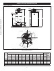
INSTALLATION CONSIDERATIONS ROUGH-IN DIMENSIONS SUPPLY GAS CONNECTION INTAKE AIR CONNECTION 3 INCH PVC WATER OUTLET HEIGHT T & P VALVE FRONT B C LOWER TEMPERATURE PROBE Printed on 2/7/2019 9:11 AM CT BACK CLEANOUT D A H 3/4” NPT RECIRCULATION RETURN F I VENT CONNECTION 3 INCH (exhaust elbow) 1 1/2” NPT WATER 3/4” NPT INLET DRAIN J G E These designs comply with the current edition of the American National Standard for Gas Water Heaters, Volume III, ANSI Z21.10.3 / CSA 4.
Table 2. Fuel Type/Connection Size by Model † MODEL SERIES NATURAL GAS PROPANE GAS 120 300/301 3/4 "NPT 3/4 "NPT 150 300/301 3/4 "NPT 3/4 "NPT 199 300/301 3/4 "NPT 3/4 "NPT 250 300/301 3/4 "NPT 3/4 "NPT † Depending on the installed equivalent length, and/or the number of appliances connected, the supply gas line size may have to be increased beyond the minimum required sizes - see Gas Line Sizing on page 39.
CIRCULATION PUMPS CLEARANCE TO COMBUSTIBLE MATERIALS The water heaters covered in this manual are approved for installation on combustible flooring. The clearance to combustible and non combustible construction materials is zero inches on the back and sides of the water heater. These water heaters are also approved for installation in an alcove.
INSTALLATION REQUIREMENTS Printed on 2/7/2019 9:11 AM CT GAS SUPPLY SYSTEMS Low pressure building gas supply systems are defined as those systems that cannot under any circumstances exceed 14” W.C. (1/2 PSI Gauge). These systems do not require pressure regulation. Measurements should be taken to ensure that gas pressures are stable and fall within the requirements stated on the water heater rating plate.
MIXING VALVES HOT WATER OUTLET Water heated to a temperature which will satisfy clothes washing, dish washing, and other sanitizing needs can scald and cause permanent injury upon contact. Short repeated heating cycles caused by small hot water uses can cause temperatures at the point of use to exceed the water heater’s temperature setting by up to 20°F (11°C).
TEMPERATURE-PRESSURE RELIEF VALVE CAUTION Water Damage Hazard Explosion Hazard • Temperature-Pressure Relief Valve discharge Temperature-Pressure Relief Valve must comply with ANSI Z21.22CSA 4.4 and ASME code. pipe must terminate at adequate drain. T&P VALVE DISCHARGE PIPE REQUIREMENTS Properly sized temperaturepressure relief valve must be installed in opening provided. • • • • • Can result in overheating and excessive tank pressure.
CONDENSATE DRAIN COMBUSTIBLE MATERIAL STORAGE The water heaters covered in this manual are condensing appliances and require a building drain to be located in close proximity to allow the condensate to drain safely. Fire or Explosion Hazard Printed on 2/7/2019 9:11 AM CT Condensate drains from the water heater at the exhaust elbow located at the bottom. The field installed condensate drain line must not be elevated above the condensate drain connection on the built-in condensate trap.
AIR REQUIREMENTS UNUSUALLY TIGHT CONSTRUCTION In unconfined spaces in buildings, infiltration may be adequate to provide air for combustion, ventilation and dilution of flue gases. However, in buildings of unusually tight construction (for example, weather stripping, heavily insulated, caulked, vapor barrier, etc.), additional air must be provided using the methods described in Confined Space (page 17).
FRESH AIR OPENINGS FOR CONFINED SPACES Alternatively a single permanent opening, commencing within 12 inches (300 mm) of the top of the enclosure, shall be provided. See Figure 10. The water heater shall have clearances of at least 1 inch (25 mm) from the sides and back and 6 inches (150 mm) from the front of the water heater.
Printed on 2/7/2019 9:11 AM CT OUTDOOR AIR THROUGH TWO VERTICAL DUCTS The illustrations shown in this section of the manual are a reference for the openings that provide fresh air into confined spaces only. When ducts are used, they shall be of the same cross sectional area as the free area of the openings to which they connect. The minimum dimension of rectangular air ducts shall be not less than 3 inches (7.62 cm). DO NOT refer to these illustrations for the purpose of vent installation.
Printed on 2/7/2019 9:11 AM CT INSTALLATION REQUIREMENTS - COMMONWEALTH OF MASSACHUSETTS COMMONWEALTH OF MASSACHUSETTS INSPECTION For all side wall terminated, horizontally vented power vent, direct vent, and power direct vent gas fueled water heaters installed in every dwelling, building or structure used in whole or in part for residential purposes, including those owned or operated by the Commonwealth and where the side wall exhaust vent termination is less than seven (7) feet above finished grade in
VENTING INSTALLATION • • AL29-4C Stainless Steel - See page 29. Breathing Hazard - Carbon Monoxide Gas • HeatFab Saf-T Vent • Duravent FasNSeal Note: The use of cellular core PVC (ASTM F891), cellular core CPVC, or Radel® (polyphenolsulfone) in nonmetallic venting systems is prohibited. Covering nonmetallic vent pipe and fittings with thermal insulation is prohibited. • Install vent system in accordance with codes.
10. Do not anchor the vent or intake air pipe directly to framed walls, floors or ceilings unless rubber isolation pipe hangers are used to prevent vibration noise from being transmitted. 11. Use only approved vent/intake air pipe sizes and materials. See Venting Requirements (page 23). 90° TO 130° 12. Use only factory supplied vent and intake air, concentric or low profile terminations. See Venting Requirements (page 23). Printed on 2/7/2019 9:11 AM CT 13.
VENTING REQUIREMENTS Four-Inch Pipe FIELD-SUPPLIED FITTINGS There is no minimum equivalent feet requirement for the intake air pipe. Field-supplied fittings should be equivalent to the piping material being installed. Field-installed/supplied fittings will add equivalent feet to the vent or intake air piping as indicated below. All field-supplied/ installed fittings and piping must be factored into the equivalent feet calculations.
VENTING INSTALLATION SEQUENCE 1. Read General Venting Instructions (page 21) and Venting Requirements (page 23) before proceeding. These instructions and requirements must be followed on all installations. 2. Determine whether the water heater will be installed in a Power Vent or Direct Vent configuration and which vent system arrangement will be used for the installation. See the various venting arrangements in Venting Arrangements (page 34). 3.
INSTALL TEE FITTING AS CLOSE TO WATER HEATER INTAKE AIR CONNECTION AS POSSIBLE FACTORY INTAKE AIR CONNECTION Breathing Hazard - Carbon Monoxide Gas Do not obstruct water heater air intake. INTAKE AIR PIPING Gas and carbon monoxide detectors are available. FIELD SUPPLIED 3” x 3” x 1/2” TEE WITH HOSE BARB FITTING INSTALLED Install water heater in accordance with the instruction manual. Printed on 2/7/2019 9:11 AM CT Breathing carbon monoxide can cause brain damage or death.
VERTICAL TERMINATION INSTALLATION 1. Determine the location for the termination(s). 2. If installing only the vent (exhaust) piping in a Power Vent configuration vertically through the roof; ensure that all exterior vertical clearance requirements shown in Figure 22 (page 26) and Figure 23 (page 27) are being maintained. These clearances and those cited by local and national codes must be maintained.
IF LESS THAN 5. In colder climates this separation should be increased to at least 48 inches (122 cm) between the intake air and vent termination or any other appliance vent that discharges moisture-laden air such as clothes dryers. This will reduce possibility of frost over from side winds blowing exhaust vapors to the intake air termination and is recommended for Canadian installations. 6.
11. The wall plates for the three-inch vent pipe are included with the heater. Wall plates for two-inch or four-inch vents are field supplied. 13. Place a bead of silicone caulking (field supplied) around the gap between the installed pipe(s) and the wall. Apply enough to fill the gap between the pipe(s) and wall. 14. Press the wall plate flush against the outside wall. Slide the included metal wall plate(s) over the pipe(s) to stop against the intake air and/or vent termination.
AL29-4C® VENT INSTALLATIONS (AL29-4C® is a registered trademark of Allegheny Technologies, Inc.) Listed vent systems composed of AL29-4C® must not mix parts from the different manufacturers. The joints of these products are sealed by internal gaskets. Do not use any other type of sealant. When assembling these vent systems, follow the vent manufacturer’s instructions for cleaning and lubricating the joints, if required.
COMMON DIRECT VENTING REQUIREMENTS The water heaters covered by this manual may be installed using a common direct vent kit. Contact your local distributer or contact Technical Support for assistance to order. See the contact information label on the water heater. 8. When installing multiple concentric terminations vertically through the roof in the same location, the termination caps for all concentric terminations must be at the same height measured from ground.
• For two-inch installations, connect the pipe directly to the two-inch termination. For three-inch installations connect the pipe directly to the three-inch termination. Do not mix different pipe and termination sizes. • For four-inch pipe installations - connect the piping to the concentric termination using field supplied 4" x 3" reducer couplings and short sections of three-inch pipe (18 inches or less).
Note: When multiple concentric terminations are installed through a roof in the same location all termination caps must be at the same height measured from the ground. Four Concentric Terminations 1. When installing four concentric terminations through a roof or through a sidewall in close proximity they may be arranged into stacked rows of two as shown in Figure 33 (page 32) or lateral rows of two as shown in Figure 34 (page 32). 2.
SIDEWALL Air Inlet Piping Vent Base Vent Cap Vent (Exhaust) Piping Printed on 2/7/2019 9:11 AM CT ROOF Figure 39. Inlet and Vent Flow in Low-Profile Vent Installation To Heater Intake Air Connection Figure 38. Eight Concentric Terminations From Heater Vent Pipe Connection LOW-PROFILE VENT TERMINATION INSTALLATION This water heater is certified for sidewall direct venting with IPEX System 636 Low Profile Vent Kit. Follow instructions below for proper installations.
Table 12. Low Profile Termination Kits - Dimensions IPEX Kit Number Part Number 100086241 196984 Description 2" Flush Mount Vent Kit 100187887 100187888 3″ Flush Mount Vent Kit 4″ Flush Mount Vent Kit 196985 196986 Pipe Outside Hole Spacing Diameter (Center to Center) 2.375" 5.63" 3.5″ 4.5″ 5.63″ 5.63″ Table 13.
Enlarged View of Direct Vent Air Intake Moisture Protection * Enlarged View of Direct Vent Air Intake Moisture Protection Printed on 2/7/2019 9:11 AM CT * * * * Figure 45. Direct Vent Horizontal * Figure 46. Direct Vent Vertical Vent Horizontal Intake Enlarged View of Direct Vent Air Intake Moisture Protection * Figure 47.
TERMINATION CLEARANCES SIDEWALL POWER VENT G H D E L B B B C M B Printed on 2/7/2019 9:11 AM CT F I B K J B Figure 51.
TERMINATION CLEARANCES SIDEWALL DIRECT VENT G HH D E L B B B C M B Printed on 2/7/2019 9:11 AM CT F I B K J B Figure 52.
WATER HEATER INSTALLATION CONDENSATE DRAIN INSTALLATION INSTALLATION INSTRUCTIONS 1. Ensure the water heater’s Enable/Disable switch is in the “Disable” position. Installation must conform with these instructions and local building codes. Field supplied materials required for installation include: • • • Printed on 2/7/2019 9:11 AM CT • Approved PVC cement and PVC primer. 1/2 inch PVC pipe - minimum length to equal the distance between the water heater and a suitable building drain.
SUPPLY GAS LINE INSTALLATION GAS LINE SIZING Depending on the developed equivalent length and/or the number of appliances connected to a common main, the size of supply gas lines may have to be increased. Contact your local gas utility company to ensure that adequate gas service is available and to review applicable installation codes for your area. Size the supply/main gas line(s) in accordance with Table 14 or Table 15.
GAS LINE LEAK TESTING GAS LINE CONNECTION The water heaters covered by this manual are shipped from the factory with 3/4 inch supply gas connections. The supply gas line must not be smaller than 3/4 inch. Connect the supply gas line to the water heater's 24-volt gas valve in accordance with all applicable local and national code requirements. 1. Any time work is done on the gas supply system perform a leak test to avoid the possibility of fire or explosion.
POWER SUPPLY CONNECTIONS To use the enable/disable circuit, it must first be activated by selecting the “Use External Enable” from the UIM. Field-supplied wiring is then installed between the water heater’s central control board (CCB) and a set of “dry contacts” (no voltage or load) on the field supplied external control. Read the requirements for the Power Supply (page 13) before connecting power.
T&P VALVE DISCHARGE PIPE WATER LINE CONNECTIONS The water piping installation must conform to these instructions and to all local and national code authority having jurisdiction. Good practice requires that all heavy piping be supported. This water heater is provided with a properly rated/sized and certified combination temperature - pressure (T&P) relief valve by the manufacturer. See Temperature-Pressure Relief Valve (page 15) for information on replacement and other requirements.
TEMPERATURE REGULATION HIGH TEMPERATURE LIMIT CONTROL (ECO) Never allow small children to use a hot water tap or draw their own bath water. Never leave a child or disabled person unattended in a bathtub or shower. This water heater is equipped with an ECO (energy cut out) non adjustable high temperature limit switch. The ECO is a normally closed switch that opens (activates) on a rise in temperature.
HIGH TEMPERATURE APPLICATIONS Higher operating temperatures cause more wear on all water heaters and will decrease the life span of the water heater. Consider installing a small booster water heater for high temperature applications, such as commercial dishwashers, to raise the outlet temperature from the larger primary water heater to the desired point of use temperature.
CONTROL SYSTEM OPERATION WI-FI The water heaters covered in this manual are equipped with an electronic control system that regulates water temperature inside the storage tank. Heating cycles and ignition are managed by the control system. The ECO (energy cut out), flame sensor, pressure switches and temperature probes are monitored by the control system. The Combustion Blower, Spark Ignition Transformer, 24-volt gas valve and anode rods are all powered by the control system.
STATUS ICONS The Status Icons are displayed on the Desktop screen and convey operational and diagnostic information. The icons are described in the table below. Table 17. Status Icons Icon Description Water temperature in the tank has fallen. Shaded area of the animated thermometer icon will rise and fall in response to water temperature in the storage tank as sensed from the Upper and Lower Temperature Probes. See Figure 3 (page 8) and Figure 4 (page 9) for location for location of Temperature Probes.
OPERATING STATES The current operational state of the water heater is displayed on the Desktop screen as the "Status." The common operational states are described in the table below. Printed on 2/7/2019 9:11 AM CT Table 18. Operating States State Description Standby The water heater is not in an active heating cycle. IE: the Tank Temperature is at or above the Operating Set Point. Input Verification The control system is conducting a diagnostic check at the beginning of a heating cycle.
USER SETTINGS & CONTROL SYSTEM MENUS When the water temperature, sensed by the control system from the two (upper and lower) Temperature Probes, reaches the Operating Set Point, the control system ends the heating cycle. A heating cycle is activated again when the sensed water temperature drops below the Operating Set Point minus the Differential setting. TEMPERATURES MENU Operating Set Point and Differential Adjustment The Operating Set Point is adjustable from 90°F (42°C) to 180°F (82°C).
Temperatures Menu Printed on 2/7/2019 9:11 AM CT Description/Action Display • Differential Mode - Operating mode with an Intelligent Demand Response (IDR). This mode allows the water heater to reduce preset differential to a lower setting so the appliance will more rapidly respond to large draws to maintain water outlet temperature. This mode is enabled at the factory by default, but can be disabled in the field if required.
ICOMM MENU Printed on 2/7/2019 9:11 AM CT iCOMM Screen Description/Action Display Wi-fi Status - displays status of wi-fi connection. Ethernet - displays status of Ethernet connection. iCOMM Server - displays status the iCOMM server. Wi-fi MAC - displays the wi-fi MAC number. Ethernet MAC - displays the Ethernet MAC number. DSN - displays the Device Serial Number (DSN). Used for registration of the heater. Wi-fi Strength - displays wi-fi signal strength as a series of bars.
HEATER STATUS MENU Heater Status Menu Description/Action Display Press Heater Status from the Main Menu to enter this menu. This menu contains non adjustable operational information. Use the slidebar to navigate the menu. Status - displays the current Operating State. See Table 18 (page 47). • ECO Contact, Low Gas PS, Blocked Inlet PS, Blocked Outlet PS, Blower Prover PS - displays the current state of the switch contacts; open or closed.
HEATER INFORMATION Description/Action Display Press Heater Information from the Main Menu to enter this menu. This menu contains non adjustable operational information. Top of Menu • • • • • Printed on 2/7/2019 9:11 AM CT • • • • • • • Elapsed Time - Total accumulated time the control system (water heater) has been energized. Burner On Time - Total accumulated time the control system has been in the heating operating state; burner run time.
FAULT HISTORY Description/Action Display Press "Fault History" from the Main Menu to enter this menu. This menu contains non adjustable operational information. Use the Slidebar to navigate the menu. Fault History This menu contains a list of the last nine (9) fault and alert messages with a time stamp. The newest event will replace the oldest. Faults will clear after 30 days. Press the fault to view details for each fault or alert message stored.
SERVICE CONTACT INFORMATION The control system has a discrete menu that Installing contractors and/or service agents can access to enter contact information for their customers. This contact information will be displayed with all fault and alert messages. Table 20. Service Contact Information Description/Action Display From the Desktop Screen press and hold down the middle (unmarked) area located between the "MENU" and "HELP" buttons for 15 seconds to activate the "Contact Information" screen.
Table 20. Service Contact Information Description/Action Display When the new Contact Name and Contact Phone number have both been updated, press "BACK" to return to the Desktop screen. Contact Information Show Contact Yes > Change Contact Name > Change Contact Phone > Current Contact Info: YOURCOMPANYNAMEHERE (123) 456-7890 Printed on 2/7/2019 9:11 AM CT BACK Access Code - Displays access code utilized to enable/disable screen lock. Enable Screen Lock - Factory default set to No.
START UP PRIOR TO START UP 5. Installation and start up of this water heater requires abilities and skills equivalent to that of a licensed tradesman in the field involved. See Qualifications (page 6). Note: The manometer tubing should be purged before taking any readings. Water heaters covered by this manual have test ports for supply and manifold gas pressure readings on the gas valve.
LIGHTING THE WATER HEATER LIGHTING OPERATION & LABELS The instruction label below is affixed to the water heaters that are covered by this manual at the factory and must be followed when lighting and operating the water heater. FOR YOUR SAFETY READ BEFORE LIGHTING WARNING: If you do not follow these instructions exactly, a fire or explosion may result causing property damage, personal injury or loss of life.
SUPPLY GAS PRESSURE ADJUSTMENT CHECKING THE FIRING RATE Supply gas pressure shall be measured while the water heater is not firing (static pressure) AND while the water heater is firing at full capacity (dynamic pressure). Follow these instructions to determine the actual firing rate of the water heater: Note: The heaters covered by this manual are capable of modulating their firing rate. The firing rate should be checked with the heater operating at it's full firing rate.
HIGH ALTITUDE INSTALLATIONS The water heaters covered by this manual are certified for use without modification for altitudes up to 10,100 feet (3,078 m). Most gas utility companies de-rate their gas for high altitudes, making it unnecessary to install high altitude orifices. Printed on 2/7/2019 9:11 AM CT Fire and Explosion Hazard Under no circumstances should the input exceed the rate shown on the water heater’s rating label. Overfiring could result in fire or explosion.
TROUBLESHOOTING INSTALLATION CHECKLIST 2. The list below represents some of the most critical installation requirements that, when overlooked, often result in operational problems, down time and needless parts replacement. This is not a complete list. Before performing any troubleshooting procedures use the list below to check for installation errors. SEQUENCE OF OPERATION Read the Sequence of Operation below before attempting to correct any operational problems.
SEQUENCE OF OPERATION FLOW CHART Sequence is shown with Enable/Disable Switch in the Enable position If tank temperature drops below Operating Set Point minus Differential setting a heating cycle is activated Printed on 2/7/2019 9:11 AM CT Control System performs diagnostic checks Normal State of all pressure switches and ECO are checked Pressure switches and ECO are verified closed NO Combustion Blower is energized Pre-Purge cycle Spark Ignition Transformer is energized 24 Volt Gas Valve is energize
OPERATIONAL PROBLEMS • • Debris clogging/blocking the intake air screen(s) - see Figure 18 (page 25) and Figure 25 (page 27). Debris clogging/blocking the Main Burner - see Figure 2 (page 7). MOMENTARY IGNITION Read and understand this instruction manual and the safety messages herein before installing, operating or servicing this water heater. Burn Hazard Failure to follow these instructions and safety messages could result in death or serious injury.
NOISY OPERATION • • DIAGNOSTIC CHECKS Sediment or lime scale accumulations can cause rumbling and pounding noises during heating cycles. See Maintenance (page 66) for sediment and lime scale removal procedures. Normal operating noise of electrical components; Combustion Blower, transformer hum, relay contact closure. Electrical Shock Hazard • Printed on 2/7/2019 9:11 AM CT WATER LEAKAGE IS SUSPECTED Turn off power at the branch circuit breaker serving the water heater before performing any service.
FAULT AND ALERT MESSAGES Contact Technical Support for further assistance or to locate a qualified service agent in your area. See the contact-information label on the water heater. Fault and Alert Messages Possible Causes - Check/Repair Printed on 2/7/2019 9:11 AM CT • • • • • • • • • • • Displayed Fault/Alert Message Using a manometer, ensure that gas supply pressure is above minimum requirement listed on heater’s data plate and does not drop more than 1.5” W.C. when unit fires.
Fault and Alert Messages Possible Causes - Check/Repair • • • • Displayed Fault/Alert Message Confirm the water heater is full of water. Confirm the powered anode wire connections are tight and free of debris or moisture (i.e. rust, solder, metal pipe shavings). Confirm proper electrical ground to the water heater. Inspect powered anode(s), clean/replace as needed. No Water 0 days 0 hrs 0 mins ago Error Code: D6 -8 No water detected by Powered Anode.
MAINTENANCE See Features and Components (page 7) for the location of the water heater components described below. GENERAL Keep water heater area clear and free from combustible materials, gasoline, and other flammable vapors and liquids. See Combustible Material Storage (page 16). Water temperature over 125°F (52°C) can cause severe burns instantly resulting in severe injury or death. Water heater maintenance includes periodic tank flushing and cleaning, and removal of lime scale.
FILLING THE WATER HEATER MANUAL LIME SCALE REMOVAL SEDIMENT REMOVAL Note: Contact your local distributor or contact Technical Support to order a new cleanout gasket. See the contact information label on the water heater. Have the new gasket available before removing the cleanout cover. Waterborne impurities consist of the particles of soil and sand which settle out and form a layer of sediment on the bottom of the tank. The cleanout opening is shown in Figure 55.
DRAIN VALVE AND ACCESS PANELS Note: Excessive water pressure is the most common cause of Temperature-Pressure Relief Valve leakage. Excessive water system pressure is most often caused by “thermal expansion” in a “closed system.” See Closed Water Systems (page 14) and Temperature-Pressure Relief Valve (page 15). The Temperature-Pressure Relief Valve is not intended for the constant relief of thermal expansion. The water heaters covered in this manual are equipped with a drain valve.
DIAGRAMS CENTRAL CONTROL BOARD (CCB) LAYOUT 6 5 4 J16 3 2 1 J13 J3 8 7 6 5 J5 4 3 2 1 J9 4 Printed on 2/7/2019 9:11 AM CT 7 8 9 10 11 12 3 1 2 3 J14 4 5 6 3 1 4 2 J15 8 5 4 3 2 1 2 1 J4 4 3 2 J10 1 2 J17 6 5 1 4 3 2 1 1 8 7 9 4 6 J1 1 3 J12 3 2 1 2 J6 4 3 2 1 Figure 66.
WIRING DIAGRAM 1 Blue No factory connections Ferrite Bead White / Blue 2 White/Blue 1 White/Red White / Red 120V 1 Red 2 Black Neutral 3 Green Ground 1 Red 2 Black BURNER BOLT CCB J16 Low Voltage In White Transformer Transformer Secondary Black 6 White/Green 5 Orange 4 Blue CCB J6 120V Out Power Supply J2 Splice 4 White/Green 3 Orange Upper Temperature Probe / ECO ECO Thermistor Thermistor ECO Dgnd 5VDC 12VDC 24VAC 24VAC Thermistor Thermistor Inlet return Outlet return / Inlet power
CIRCULATION PUMP WIRING DIAGRAMS NOTE: USE SEPARATE 120 VAC POWER SUPPLY FOR PUMP CIRCUIT. DO NOT SHARE POWER WITH WATER HEATER AS THIS MAY CAUSE ELECTRICAL LINE NOISE AND LEAD TO ERRATIC CONTROL SYSTEM OPERATION. FIELD SUPPLIED TEMPERATURE CONTROL INSTALLED IN THE STORAGE TANK OR CIRCULATING LOOP RETURN LINE L1 HOT Printed on 2/7/2019 9:11 AM CT 120 VAC POWER CIRC PUMP MOTOR L2 NEUTRAL Figure 68.
See Dish-washing Machines (page 14). See Temperature-Pressure Relief Valve (page 15). 2. 3. HOT WATER TO FIXTURES FULL PORT BALL VALVE CIRCULATING PUMP EXPANSION TANK COLD WATER SUPPLY WATER FLOW SWITCH DRAIN PRESSURE RELIEF VALVE HOT WATER RETURN TEMPERATURE GAGE TEMPERATURE CONTROL PROBE TEMPERATURE & PRESSURE RELIEF VALVE CHECK VALVE If a pump is being installed in a recirculation loop between the water heater and a commercial dishwasher wire according to Figure 69 (page 71). 7.
See Thermal Expansion and Closed Water Systems (page 14). 4. EXPANSION TANK TEMPERED WATER OUTLET HOT WATER RETURN OUTLET PIPE T&P TO OPEN DRAIN COLD HOT CIRCULATING PUMP PRESSURE RELIEF VALVE TEMPERATURE & PRESSURE RELIEF VALVE NOTES: 1. Preferred piping method. 2. The temperature and pressure relief valve setting shall not exceed pressure rating of any component in the system. 3. Service valves are shown for servicing unit. However, local codes shall govern their usage.
See Dish-washing Machines (page 14). See Temperature-Pressure Relief Valve (page 15). See Thermal Expansion and Closed Water Systems (page 14). 2. 3. 4. ALT.
See Dish-washing Machines (page 14). See Temperature-Pressure Relief Valve (page 15). See Thermal Expansion and Closed Water Systems (page 14). See Water Line Connections (page 42). 2. 3. 4. 5. ALTERNATE LOCATION EXPANSION TANK COLD WATER SUPPLY CIRCULATING PUMP HOT WATER RETURN WATER FLOW SWITCH FULL PORT BALL VALVE CIRCULATING PUMP HOT WATER TO FIXTURES TEMPERATURE GAGE CHECK VALVE DRAIN TEMPERATURE CONTROL PROBE PRESSURE RELIEF VALVE NOTES: 1. Preferred piping method. 2.
See Temperature-Pressure Relief Valve (page 15). See Thermal Expansion and Closed Water Systems (page 14). See Water Line Connections (page 42). 3. 4. 5.
See Dish-washing Machines (page 14). See Temperature-Pressure Relief Valve (page 15). See Thermal Expansion and Closed Water Systems (page 14). See Water Line Connections (page 42). 2. 3. 4. 5.
PIPE T&P TO OPEN DRAIN PIPE T&P TO OPEN DRAIN PIPE T&P TO OPEN DRAIN WATER FLOW SWITCH FULL PORT BALL VALVE CIRCULATING PUMP EXPANSION TANK COLD WATER SUPPLY HOT WATER RETURN TANK TEMPERATURE CONTROL TEMPERATURE GAGE DRAIN PRESSURE RELIEF VALVE CHECK VALVE TEMPERATURE CONTROL PROBE TEMPERATURE & PRESSURE RELIEF VALVE NOTES: 1. Preferred piping method. 2. The temperature and pressure relief valve setting shall not exceed pressure rating of any component in the system. 3.
Printed on 2/7/2019 9:11 AM CT NOTES 79
Printed on 2/7/2019 9:11 AM CT Copyright © 2018. All rights reserved.