
A.O. Smith Cyclone Mxi Installation Manual
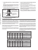

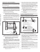
Table Of Contents
- Safe Installation, Use, and Service
- APPROVALS
- General Safety Information
- Introduction
- Features and Components
- Installation Considerations
- Installation Requirements
- Gas Supply Systems
- Supply Gas Regulator
- Power Supply
- Power Fluctuations and Electrical Noise
- Mixing Valves
- Dish-washing Machines
- Closed Water Systems
- Thermal Expansion
- Temperature-Pressure Relief Valve
- Condensate Drain
- Combustible Material Storage
- Contaminated Air
- Air Requirements
- Fresh Air Openings For Confined Spaces
- Outdoor Air Through One Opening
- Installation Requirements - Commonwealth of Massachusetts
- Venting Installation
- General Venting Information
- Category IV Appliances
- General Venting Instructions
- Venting Requirements
- Common Direct Venting
- Venting Installation Sequence
- Power Vent Installation
- Direct Vent Installation
- Vertical Termination Installation
- Polypropylene Installations
- AL29-4C® Vent Installations
- Common Direct Venting Requirements
- Concentric Termination Installation Preparation
- Concentric Termination Installation
- Low-Profile Vent Termination installation
- Venting Arrangements
- Termination Clearances Sidewall Power Vent
- Termination Clearances Sidewall Direct Vent
- Water Heater Installation
- Temperature Regulation
- Control System Operation
- Start Up
- Lighting the Water Heater
- Troubleshooting
- Maintenance
- Diagrams
- Notes

23
VENTING REQUIREMENTS
FIELD-SUPPLIED FITTINGS
Field-supplied ttings should be equivalent to the piping material
being installed. Field-installed/supplied ttings will add equivalent feet
to the vent or intake air piping as indicated below. All eld-supplied/
installed ttings and piping must be factored into the equivalent feet
calculations.
• 90° elbows (short or long radius) are equivalent to 5 linear
feet (152 cm) of pipe.
• 45° elbows (short or long radius) are equivalent to 2.5 linear
feet (76 cm) of pipe.
PRIMER AND CEMENT
Tetrahydrofuran (THF) primer should be used to prepare the surfaces
of pipe and ttings for solvent welding. If CPVC or ABS pipe and
ttings are used, then the proper cement must be used for all joints,
including joining the pipe to the factory provided terminations (PVC
material). PVC Materials should use ASTM D-2564 Grade Cement;
CPVC Materials should use ASTM F-493 Grade Cement.
PIPE SIZE REQUIREMENTS
The water heaters covered in this manual are certied for the use
of two-, three-, and four-inch pipe for the vent (exhaust) and intake
air piping. If the installed equivalent length for the intake air or vent
piping will be 50 feet (15.2 m) or less, two- or three-inch pipe must
be used. If the installed equivalent length will be more than 50 feet
(15.2 m), four-inch pipe must be used.
Note: Install the pipe size required for the installed equivalent
length of each pipe independently. That is, if the intake
air pipe will be 50 equivalent feet or less and the vent
pipe will be more than 50 equivalent feet, the intake air
pipe must be installed using three-inch pipe and the
vent must be installed using four-inch pipe.
MAXIMUM EQUIVALENT LENGTHS
Two-Inch Pipe
The 120, 150, and 199 models are certied for a maximum equivalent
vent length of 40 feet (12.1 m). The 250 model is certied for a
maximum equivalent vent length of 20 feet (6.1 m). The maximum
equivalent length for the air inlet pipe is the same as the vent pipe.
Three-Inch Pipe
The water heaters covered in this manual are certied to a maximum
length of three-inch pipe for the exhaust venting arrangement of 50
equivalent feet (15.2 m). The certied maximum length of three-inch
pipe for intake air piping is also 50 equivalent feet (15.2 m). On Direct
Vent installations, both pipes can be up to 50 equivalent feet (15.2 m).
Four-Inch Pipe
The water heaters covered in this manual are certied to a maximum
length of four-inch pipe for the exhaust venting arrangement of 120
equivalent feet (36.5 m). The certied maximum length of four-inch
pipe for intake air piping is also 120 equivalent feet (36.5 m). On
Direct Vent installations, both pipes can be up to 120 equivalent
feet (36.5 m).
MINIMUM EQUIVALENT LENGTHS
Two-Inch Pipe
The water heaters covered in this manual are certied to a minimum
equivalent length of 2 inch pipe of 12 feet ( 3.7 m). There is no
minimum equivalent feet requirement for the intake air pipe.
Three-Inch Pipe
The water heaters covered in this manual are certied to a minimum
length of three-inch pipe for the vent (exhaust) of seven equivalent
feet (2.1 m). There is no minimum equivalent feet requirement for
the intake air pipe.
Four-Inch Pipe
There is no minimum equivalent feet requirement for the intake air
pipe.
Optionally, the heater may use four-inch diameter vent for equivalent
lengths of 50 to 120 feet. For short equivalent lengths (depending on
heater size), a two-inch pipe option is also available. These optional
vent diameters must conform to
Table 7
(page 23)
and use eld
supplied terminals and wall plates.
MAXIMUM NUMBER OF ELBOWS
The maximum number of elbows allowed varies according to the
heater input rating and pipe diameter. See
Table 7
(page 23).
FACTORY-SUPPLIED FITTINGS
The water heater ships with two factory-supplied three-inch
terminations (PVC 45° elbows with debris screen). Factory-supplied
vent and intake air terminations, concentric, or low-prole terminations
must be used. Factory-supplied terminations and installed ttings
(exhaust/condensate elbow and intake air connection) add zero
equivalent feet to the vent and intake air piping.
Table 7. PVC/CPVC Equivalent Length and
Maximum Number of Elbows
Model
Equivalent Vent Length Max Elbows
2" 3" 4" 2" 3" 4"
120
12' to 40' 7' to 50' 50' to 120' 4 4 6
150 12' to 40' 7' to 50' 50' to 120' 4 4 6
199
12' to 40' 7' to 50' 50' to 120' 4 4 6
250 12' to 20'
7' to 50' 50' to 120' 2 4 6
Note: Refer to
Table 10
and
Table 11
beginning on page 29 for
the equivalent linear pipe length of AL29-4C
®
45° and
90° elbows.
FOUR-INCH VENT TERMINATIONS
When four-inch intake air or vent pipe is installed, factory supplied
four-inch terminations must be used. Contact your local distributor
or contact Technical Support to order four-inch termination(s). See
the contact information label on the water heater.
OPTIONAL CONCENTRIC & LOW PROFILE TERMINATIONS
The water heaters covered by this manual may be installed in a
Direct Vent conguration using a concentric termination or a low-
prole termination.
Concentric and Low-Prole terminations must be ordered separately.
Contact your local distributer or contact Technical Support for
assistance. See the contact information label on the water heater.
The following are the part numbers for the different pipe diameters:
• Two-Inch Concentric Termination #100153586
• Two-Inch Low-Prole Termination #100086241
• Four-Inch Concentric Termination # 100111100 (used for
both three- and four-inch diameter piping)
• Three-Inch Low-Prole Termination # 100187887
• Four-Inch Low-Prole Termination # 100187888
COMMON DIRECT VENTING
The water heaters covered by this manual may be installed using
a common direct vent kit. Contact your local distributer or contact
Technical Support for assistance. See the contact information label
on the water heater.
Printed on 2/7/2019 9:11 AM CT