
A.O. Smith Cyclone Mxi Installation Manual
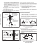
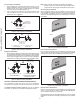
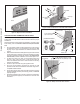
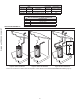
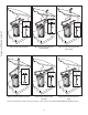
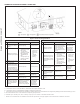
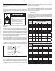
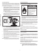
Table Of Contents
- Safe Installation, Use, and Service
- APPROVALS
- General Safety Information
- Introduction
- Features and Components
- Installation Considerations
- Installation Requirements
- Gas Supply Systems
- Supply Gas Regulator
- Power Supply
- Power Fluctuations and Electrical Noise
- Mixing Valves
- Dish-washing Machines
- Closed Water Systems
- Thermal Expansion
- Temperature-Pressure Relief Valve
- Condensate Drain
- Combustible Material Storage
- Contaminated Air
- Air Requirements
- Fresh Air Openings For Confined Spaces
- Outdoor Air Through One Opening
- Installation Requirements - Commonwealth of Massachusetts
- Venting Installation
- General Venting Information
- Category IV Appliances
- General Venting Instructions
- Venting Requirements
- Common Direct Venting
- Venting Installation Sequence
- Power Vent Installation
- Direct Vent Installation
- Vertical Termination Installation
- Polypropylene Installations
- AL29-4C® Vent Installations
- Common Direct Venting Requirements
- Concentric Termination Installation Preparation
- Concentric Termination Installation
- Low-Profile Vent Termination installation
- Venting Arrangements
- Termination Clearances Sidewall Power Vent
- Termination Clearances Sidewall Direct Vent
- Water Heater Installation
- Temperature Regulation
- Control System Operation
- Start Up
- Lighting the Water Heater
- Troubleshooting
- Maintenance
- Diagrams
- Notes

34
Table 12. Low Prole Termination Kits - Dimensions
Kit Number
IPEX
Part Number Description
Pipe Outside
Diameter
Hole Spacing
(Center to Center)
100086241 196984 2" Flush Mount Vent Kit 2.375" 5.63"
100187887 196985 3″ Flush Mount Vent Kit 3.5″ 5.63″
100187888 196986 4″ Flush Mount Vent Kit 4.5″ 5.63″
Table 13. Contents of Low Prole Termination Kit
Qty Item Description
1 Base (two holes)
1 Cap (one hole)
8 Stainless Steel Screws
4 Plastic Anchors
VENTING ARRANGEMENTS
Figure 42. Power Vent Vertical
Figure 43. Power Vent Horizontal
*
*
Enlarged View of
Direct Vent Air Intake
Moisture Protection
Figure 44. Direct Vent Vertical
*Direct Vent combustion air intake drains are required in certain situations. See
Direct Vent Air Intake Moisture Protection
(page 25).
Printed on 2/7/2019 9:11 AM CT