
A.O. Smith Cyclone Mxi Installation Manual
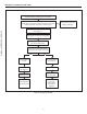
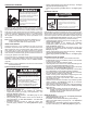

Table Of Contents
- Safe Installation, Use, and Service
- APPROVALS
- General Safety Information
- Introduction
- Features and Components
- Installation Considerations
- Installation Requirements
- Gas Supply Systems
- Supply Gas Regulator
- Power Supply
- Power Fluctuations and Electrical Noise
- Mixing Valves
- Dish-washing Machines
- Closed Water Systems
- Thermal Expansion
- Temperature-Pressure Relief Valve
- Condensate Drain
- Combustible Material Storage
- Contaminated Air
- Air Requirements
- Fresh Air Openings For Confined Spaces
- Outdoor Air Through One Opening
- Installation Requirements - Commonwealth of Massachusetts
- Venting Installation
- General Venting Information
- Category IV Appliances
- General Venting Instructions
- Venting Requirements
- Common Direct Venting
- Venting Installation Sequence
- Power Vent Installation
- Direct Vent Installation
- Vertical Termination Installation
- Polypropylene Installations
- AL29-4C® Vent Installations
- Common Direct Venting Requirements
- Concentric Termination Installation Preparation
- Concentric Termination Installation
- Low-Profile Vent Termination installation
- Venting Arrangements
- Termination Clearances Sidewall Power Vent
- Termination Clearances Sidewall Direct Vent
- Water Heater Installation
- Temperature Regulation
- Control System Operation
- Start Up
- Lighting the Water Heater
- Troubleshooting
- Maintenance
- Diagrams
- Notes

63
NOISY OPERATION
• Sediment or lime scale accumulations can cause rumbling
and pounding noises during heating cycles. See
Maintenance
(page 66) for sediment and lime scale removal procedures.
• Normal operating noise of electrical components;
Combustion Blower, transformer hum, relay contact closure.
WATER LEAKAGE IS SUSPECTED
• Ensure the water heater drain valve is tightly closed.
• Check cleanout opening for leaks - see
Figure 4
(page 9).
• Check inlet/outlet water connections and system piping.
• Check the Temperature-Pressure Relief Valve.
• Excessive water temperature.
• Excessive water pressure.
• Defective Temperature-Pressure Relief Valve.
Note: Excessive water pressure is the most common cause of
Temperature-Pressure Relief Valve leakage. Excessive
water system pressure is most often caused by "thermal
expansion" in a "closed system." See
Thermal Expansion
and
Closed Water Systems
(page 14). The Temperature-
Pressure Relief Valve is not intended for the constant
relief of thermal expansion.
Temperature-Pressure Relief Valve leakage due to pressure build
up in a closed system that does not have a thermal expansion tank
installed is not covered under the limited warranty.
Thermal expansion tanks must be installed on all closed water
systems.
REPLACEMENT PARTS
Replacement parts may be ordered from the manufacturer,
authorized service agencies or distributors. When ordering parts
be sure to have the complete water heater Model Number, Serial
Number and Series Number available. This information can be found
on the rating label afxed to the water heater.
Refer to the parts list included with the water heater from the factory
for more information or contact Technical Support for assistance.
See the contact information label on the water heater.
FAULT AND ALERT CONDITIONS
FAULT CONDITIONS
When the control system declares a fault condition it will display a
fault message on the control system's LCD with an exclamation "!"
mark. The control system will lock out and disable heating operation
until the condition is corrected. The water heater must be serviced
by a qualied service agent before operation can be restored.
ALERT CONDITIONS
When the control system declares an alert condition it will display an
alert message on the control system's LCD with a question "?" mark.
The water heater will continue to operate during an alert condition
but the water heater must be serviced by a qualied service agent
as soon as possible.
RESETTING CONTROL SYSTEM LOCK OUTS
To reset the control system from a lock out condition; turn the power
supply off at the breaker for approximately 20 seconds and then back
on. Keep in mind; if the condition that caused the fault has not been
corrected, the control system will continue to lock out.
DIAGNOSTIC CHECKS
Turn off power at the branch circuit
breaker serving the water heater
before performing any service.
Electrical Shock Hazard
•
Label all wires prior to disconnecting
when performing service. Wiring errors
can cause improper and dangerous
operation.
•
Verify proper operation after servicing.
•
Failure to follow these instructions can
result in personal injury or death.
•
The following section,
Fault and Alert Messages
(page 64), lists some
of the messages the control system will display on the LCD when
there are operational problems. This is not a complete list. Along
with each of the fault and alert messages described there will be a
list of possible causes and things to check and repair.
Only qualied service agents, as dened in
Qualifications
(page
6), using appropriate test equipment, should perform any service
procedures on the water heater.
Note: If you are not qualied and licensed or certied as
required by the authority having jurisdiction to perform
a given task do not attempt to perform any of the
diagnostic or service procedures described in the
following section.
If you do not understand the instructions in the following section do
not attempt to perform any procedures.
Contact Technical Support for further assistance or to locate a
qualied service agent in your area. See the contact information
label on the water heater.
Jumping out control circuits or components can
result in property damage, personal injury or death.
Service should only be performed by a qualified service
technician using proper test equipment.
•
Altering the water heater controls and/or wiring in any way
could result in permanent damage to the controls or water
heater and is not covered under the limited warranty.
•
Any bypass or alteration of the water
heater controls and/or wiring will result
in voiding the appliance warranty.
Printed on 2/7/2019 9:11 AM CT