MODELS BTR(C)120 THRU 500A COMMERCIAL GAS, GLASS-LINED, TANK-TYPE WATER HEATER • INSTALLATION • OPERATION • MAINTENANCE • LIMITED WARRANTY Thank you for buying this energy efficient water heater from A.O. Smith Water Products Company. We appreciate your confidence in our product. CAUTION TEXT PRINTED OR OUTLINED IN RED CONTAINS INFORMATION RELATIVE TO YOUR SAFETY. PLEASE READ THOROUGHLY BEFORE INSTALLING AND USING THIS APPLIANCE. A DIVISION OF A. O.
ROUGH-IN-DIMENSIONS MODELS BTR(C) 120 THROUGH 500 See Models Below FIGURE 1 BTR MODELS 120 THROUGH 500A - TABLE 1A MODEL BTR120 BTR154 BTR180 BTR197 BTR198 BTR199 BTR 200 BTR 250 BTR 251 BTR 275 BTR 305 BTR 365 BTR 400 BTR 500 INPUT RATE BTU/Hr. 120,000 BTU/Hr. 35 Kw/Hr 154,000 BTU/Hr 45 Kw/Hr 180,000 BTU/Hr 53 Kw/Hr 199,000 BTR/Hr 58 kW/Hr 199,000 BTU/Hr.
TABLE 1C - HEATER PERFORMANCE DATA BTR MODELS MODEL BTR 120 BTR 154 BTR 180 BTR 197 BTR 198 BTR 199 BTR 200 BTR 250 BTR 251 BTR 275 BTR 305 BTR 365 BTR 400 BTR 500 INPUT APPROX. RATE GAL EFF. BTUH CAP.
TABLE OF CONTENTS Page Page Grounding Instructions --------------------------------------------- 15 Heater Wiring --------------------------------------------------------- 15 INSTALLATION DIAGRAMS ----------------------------------- 15-21 MANIFOLDS ----------------------------------------------------------- 22 MECHANICAL VENTING ------------------------------------------- 23 Single Unit Installation --------------------------------------------- 23 Vent Installation -----------------------------------------
GENERAL SAFETY INFORMATION LIQUID PETROLEUM MODELS Water heaters for propane or liquefied petroleum gas (LPG) are different from natural gas models. A natural gas heater will not function safely on LP gas and no attempt should be made to convert a heater from natural gas to LP gas. PRECAUTIONS LP gas must be used with great caution. It is highly explosive and heavier than air. It collects first in the low areas making its odor difficult to detect at nose level.
The input reduction is primarily achieved by reducing the size of the main burner orifices. To do this, the main burner orifices require replacement with orifices sized for the particular installation elevation. Correct orifice sizing and parts may be obtained from A.O. Smith Water Products Company. When ordering, be sure to state the model number and the altitude of the location where the water heater is being installed. • Do not cover the instruction manual.
Continued manual resetting of high limit control, preceded by higher than usual water temperature is evidence of high limit switch operation. The following is a possible reason for high limit switch operation. Service Division, 5621 W. 115th Street, Alsip, IL 60803, 1-800433-2545, Canada, contact A.O. Smith Enterprises LTD., P.O. Box, 310 - 768 Erie Street, Stratford, Ontario, Canada N5A 6T3, 1-800-265-8520.
The National Sanitation Foundation also recommends circulation of 1800F (82°C) water. Where this is done, the circulation should be very gentle so that it does not cause any unnecessary turbulence inside the water heater. The circulation should be just enough to provide 1800F (82°C) water at the point of take-off to the dishwashing machine. Adjust flow by means of the plug cock in the circulating line. NEVER BE PLACED ON OR ADJACENT TO THE HEATER.
ILLUSTRATION OF MINIMUM COMBUSTIBLE CLEARANCES IN AN ALCOVE FIGURE 6 A service clearance of 24" (61cm) should be maintained from serviceable parts, such as relief valves, flue baffles, flue damper devices, thermostats, cleanout openings or drain valves. AIR REQUIREMENTS REFER TO THE LATEST EDITION OF THE "NATIONAL FUEL GAS CODE" ANSI Z223.1/NFPA 54. FOR CANADA CONSULT CAN/CSA B149.1-00.
CONFINED SPACE This water heater must be vented in compliance with all local codes, the current revision of the National Fuel Gas Code (ANSIZ223.1) and with the Category I Venting Tables. When drawing combustion and dilution air from inside a conventionally constructed building to a confined space, such a space shall be provided with two permanent openings, ONE IN OR WITHIN 12 INCHES (30.5cm) OF THE ENCLOSURE TOP AND ONE IN OR WITHIN 12 INCHES (30.5cm) OF THE ENCLOSURE BOTTOM.
TECHNICAL DATA VENTING, TABLE 3 TYPE B GAS VENT Multiple Gas Fired Tank-Type Heaters When venting mutiple tank type heaters using Type B vent pipe, follow the installation diagram (figure 8) and tables below which give sizing and data based upon NFPA 54/ANSI Z223. 1992.
TECHNICAL DATA VENTING, TABLE 3 (Continued) MODEL BTR(C)-250, 251 Input: 250,000, 251,000 Draft Hood: 6” Number of Heaters 2 3 4 MODEL BTR(C)-275 Input: 275,000 Btuh Draft Hood: 6” Numbers of Heaters 2 3 4 MODEL BTR(C)-305 Input: 305,000 Btuh Draft Hood: 8” Number of Heaters 2 3 4 MODEL BTR(C)-365, 400 Input: 365,000, 399,000 Draft Hood: 8” Number of Heaters 2 3 4 Input Btuh 250/251,000 250/251,000 250/251,000 Combined Input in Thousands of Btuh 480 500/502 720 750/753 960/1000/1004 Rise 1 Ft. 3 Ft.
also be installed with a properly sized, rated and approved combination temperature (ANSI) and pressure (ASME) relief valve(s). If a water heater is installed in a closed water system, contact the water supplier or local plumbing inspector on how to control this situation. WARNING WATER (POTABLE) HEATING AND SPACE HEATING 1. All piping components connected to this unit for space heating applications shall be suitable for use with potable water.
GAGE- 3.5 kPa) SUPPLY GAS PRESSURE. EXPOSURE TO HIGHER SUPPLY PRESSURE MAY CAUSE DAMAGE TO THE GAS VALVE WHICH COULD RESULT IN FIRE OR EXPLOSION. IF OVERPRESSURE HAS OCCURRED SUCH AS THROUGH IMPROPER TESTING OF GAS LINES OR EMERGENCY MALFUNCTION OF THE SUPPLY SYSTEM, THE GAS VALVE MUST BE CHECKED FOR SAFE OPERATION. MAKE SURE THAT THE OUTSIDE VENTS ON THE SUPPLY REGULATORS AND THE SAFETY VENT VALVES ARE PROTECTED AGAINST BLOCKAGE. THESE ARE PARTS OF THE GAS SUPPLY SYSTEM, NOT THE HEATER.
Do not subject the combination gas valve to inlet gas pressures of more than 14.0" W.C. (3.48 kPa) - natural gas, 14.0" W.C. (3.48 kPa)- propane gas. A service regulator is necessary if higher gas pressures are encountered. BEFORE PLACING THE HEATER IN OPERATION, CHECK FOR GAS LEAKAGE. Use soap and water solution or other material acceptable for the purpose in locating the leaks. DO NOT USE MATCHES, CANDLES, FLAME OR OTHER SOURCES OF IGNITION FOR THIS PURPOSE.
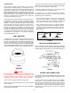
VERTICAL STORAGE TANK AND FORCED CIRCULATION DANGER TEMPERATURE SETTING SHOULD NOT EXCEED SAFE USE TEMPERATURE AT FIXTURES. SEE WATER TEMPERATURE CONTROL WARNING ON PAGE 27. IF HIGHER PREHEAT TEMPERATURES ARE NECESSARY TO OBTAIN ADEQUATE BOOSTER OUTPUT, ADD AN ANTISCALD VALVE FOR HOT WATER SUPPLIED TO FIXTURES.
TWO TEMPERATURE - ONE HEATER HIGH TEMPERATURE STORAGE WITH RECIRCULATION OF SANITIZING LOOP DANGER NOTE 1: TOGGLE SWITCH CONTROLS 180°F (82°C) WATER CIRCULATION. INSTALL ON OR CLOSE TO DISHWASHING MACHINE. TOGGLE SWITCH MUST BE CLOSED (ON) DURING THE RINSE OPERATION AND OPEN (OFF) WHEN DISHWASHER IS NOT OPERATING OR WHEN ON LONG STANDBY. TEMPERATURE SETTING SHOULD NOT EXCEED SAFE USE TEMPERATURE AT FIXTURES. SEE WATER TEMPERATURE CONTROL WARNING ON PAGE 27.
INSTALLATION DIAGRAMS-SIDE INLET/OUTLET USAGE A listed temperature and pressure relief valve of adequate capacity is installed on the heater. The locations shown in the installation diagrams on the following pages are typical. The discharge opening of the temperature and pressure relief valve must be piped to an open drain and should not be subject to freezing conditions. DO NOT REDUCE, BLOCK OR PLUG THE DISCHARGE OPENING OF THE VALVE.
ONE OR TWO TEMPERATURE - ONE HEATERS,HIGH TEMPERATURE STORAGE WITH OR WITHOUT RECIRCULATION HEATER WITH OR WITHOUT MIXING VALVE DANGER TEMPERATURE SETTING SHOULD NOT EXCEED SAFE USE TEMPERATURE AT FIXTURES. SEE WATER TEMPERATURE CONTROL WARNING ON PAGE 27. IF HIGHER PREHEAT TEMPERATURES ARE NECESSARY TO OBTAIN ADEQUATE BOOSTER OUTPUT, ADD AN ANTI-SCALD VALVE FOR HOT WATER SUPPLIED TO FIXTURES. HEATER WITH MIXING VALVE AND RECIRCULATED SANITIZING LOOP NOTE 1: * PIPE RELIEF VALVE TO OPEN DRAIN.
TWO TEMPERATURE - TWO PRE-HEATERS WITH MIXING VALVE OR BOOSTER HEATER WITH OR WITHOUT BUILING RECIRCULATION TWO PRE-HEATERS WITH MIXING VALVE DANGER TEMPERATURE SETTING SHOULD NOT EXCEED SAFE USE TEMPERATURE AT FIXTURES. SEE WATER TEMPERATURE CONTROL WARNING ON PAGE 27. IF HIGHER PREHEAT TEMPERATURES ARE NECESSARY TO OBTAIN ADEQUATE BOOSTER OUTPUT, ADD AN ANTI-SCALD VALVE FOR HOT WATER SUPPLIED TO FIXTURES.
MEDIUM TEMPERATURE - ONE HEATER WITH AUXILIARY STORAGE TANK FORCED CIRCULATION WITH OR WITHOUT BUILDING RECIRCULATION VERTICAL STORAGE TANK * PIPE RELIEF VALVE TO OPEN DRAIN. **WHEN USING AN A.O. SMITH T-140, 200, -350 OR -400 STORAGE TANK, USE LOWER 3/4” OPENING FOR TANK TEMPERATURE CONTROL. IF BUILDING CIRCULATING LOOP IS USED, CONNECT TO AN OPENING NEAR THE BOTTOM OF THE TANK.
MANIFOLD KITS TWO UNIT MANIFOLD KIT (PART NO. 195686) DIMENSIONS “A” INCHES (CM) MODEL LOW PROFILE VERTICAL HOOD “A” BTR MODELS BTRC MODELS 120 69.75” (177cm) 69.75” (177cm) 154 73.00” (185cm) 73.00” (185cm) 180 67.50” (171cm) 70.50” (179cm) 197 75.00 (192cm) 81.50” (207cm) 198 75.00” (192cm) N/A 199 67.50” (171cm) 70.50” (179cm) 200 72.00” (183cm) 72.00” (183cm) 250 72.00” (183cm) 72.00” (183cm) 251 75.00” (191cm) 75.00” (191cm) 275 72.00” (183cm) 72.00” (183cm) 305 75.00” (191cm) 75.00” (191cm) 365 79.
MECHANICAL VENTING See side wall vent kit installation manual for complete instructions. SINGLE UNIT INSTALLATION MULTIPLE UNIT INSTALLATIONS When mechanical venting of these heaters is desired, the following kits are available. For multiple unit installations, contact A.O. Smith Water Products Company, Technical Support Center at 1-800-527-1953. In Canada, contact A.O. Smith Enterprises, Ltd. at 1-800-265-8520. BTR(C) 120 through the BTR(C) 200/A A. O.
OPERATION PURGING Gas line purging is required with new piping or systems in which air has entered. IMPORTANT A qualified person must perform the initial firing of the heater. At this time the user should not hesitate to ask the individual any questions which they may have in regard to the operation and maintenance of the unit. CAUTION PURGING SHOULD BE PERFORMED BY PERSONS EXPERIENCED IN THIS TYPE GAS SERVICE.
FOR YOUR SAFETY READ BEFORE OPERATING WARNING: IF YOU DO NOT FOLLOW THESE INSTRUCTIONS EXACTLY A FIRE OR EXPLOSION MAY RESULT CAUSING PROPERTY DAMAGE, PERSONAL INJURY OR LOSS OF LIFE. A. B. THIS APPLIANCE IS EQUIPPED WITH AN IGNITION DEVICE WHICH AUTOMATICALLY LIGHTS THE PILOT. DO NOT TRY TO LIGHT THE PILOT BY HAND. BEFORE OPERATING SMELL ALL AROUND THE APPLIANCE AREA FOR GAS . BE SURE TO SMELL NEXT TO THE FLOOR BECAUSE SOME GAS IS HEAVIER THAN AIR AND WILL SETTLE ON THE FLOOR.
FOR YOUR SAFETY READ BEFORE OPERATING WARNING: IF YOU DO NOT FOLLOW THESE INSTRUCTIONS EXACTLY A FIRE OR EXPLOSION MAY RESULT CAUSING PROPERTY DAMAGE, PERSONAL INJURY OR LOSS OF LIFE. A. B. THIS APPLIANCE IS EQUIPPED WITH AN IGNITION DEVICE WHICH AUTOMATICALLY LIGHTS THE PILOT. DO NOT TRY TO LIGHT THE PILOT BY HAND. BEFORE OPERATING SMELL ALL AROUND THE APPLIANCE AREA FOR GAS . BE SURE TO SMELL NEXT TO THE FLOOR BECAUSE SOME GAS IS HEAVIER THAN AIR AND WILL SETTLE ON THE FLOOR.
ADJUSTMENTS that attach to faucets to limit hot water temperatures. Contact a licensed plumber or the local plumbing authority. ON INITIAL STARTUP SOME ADJUSTMENTS ARE NECESSARY. The water temperature is controlled by a thermostat, Fig. 3, which has two sensing elements. One sensor is located near the top of the tank and the other is near the center. The thermostat is set in the lowest position before the heater leaves the factory. 1. CHECK MANIFOLD AND INLET GAS PRESSURES. 2.
2. Inspect the venting system for proper size and horizontal pitch, as required in the National Fuel Gas Code, ANSI Z223.1 or the CAN/CGA B149 Installation codes and these instructions. Determine that there is no blockage or restriction, leakage, corrosion and other deficiencies which could cause an unsafe condition. • The pilot flame should envelop sensing device with 5/8" (1.6cm) flame, fig. 17. Remove pilot adjustment cover screw, fig. 16.
TYPICAL PILOT AND MAIN BURNER FLAMES If the gas valve becomes defective, repairs should not be attempted. A new valve should be installed in place of the defective one. CHECKING THE INPUT For appliance installation locations with elevations above 2000 feet (610 m), refer to HIGH ALTITUDE INSTALLATIONS section of this manual for input reduction procedure. FIGURE 17 1. Attach a pressure gauge or a manometer to the gauge port and refer to Table 5, for correct manifold pressure.
the factory installed magnesium anodes with aluminum anodes may correct the condition. VENTING SYSTEM Examine the venting system every six months for obstructions and/or deterioration of the vent piping. Occasionally water softener companies recommend removal of heater anodes for odor reasons. Remove all soot or other obstructions from chimney which will retard free draft. CAUTION Unauthorized removal of the anode(s) will void the warranty. For further information contact your dealer.
cleanout. UN•LIME® and the booklet may be obtained through your A. O. Smith dealer or distributor. 3. Remove six (6) hex head screws securing tank cleanout plate and remove plate. 4. Remove lime, scale, or sediment using care not to damage the glass lining. 5. Inspect cleanout plate gasket, if new gasket is required, replace with A. O. Smith part no. 99038. 6. Install cleanout plate. Be sure to draw plate up tight by tightening screws securely. 7. Replace outer jacket cover plate.
1. With the 5 gallon Up-N-Down container in the vertical position, unscrew the plastic vent cap in the handle and pierce the plastic membrane over the vent boss under the cap to allow the container to vent. — Check that after following the appliance OPERATING INSTRUCTIONS, the “Top Knob” of the appliance gas valve is in “ON” position. — Check electrical supply to the appliance for possible blown (or tripped) fusing or power interruption.
EFFIKAL RVGP-KSF-SERIES FLUE DAMPER TROUBLE SHOOTING GUIDE Do not turn damper open manually or motor damage will result, use the service switch. All readings are taken from harness receptacle. Do not push meter leads into harness receptacle. This opens the pins and will create connection problems. Effikal Pinouts & wire colors 1. Brown 2. Orange 3. Yellow 4. Black PIN END VIEW Adapter wire colors in* Black Yellow Red White *See Connection Diagram, Figure 14. NOTE: DAMPER DISC SHOWN IN OPEN POSITION.
OPERATIONAL CHECKLIST This checklist in conjunction with “TROUBLESHOOTING” and the “SEQUENCE OF OPERATION” should be used as an on-the-job troubleshooting guide to identify the cause of incorrect system operation and suggest a remedy for its correction. Because improper piping and wiring can result in unsatisfactory system performance, it is suggested that the installation by examined before using the checklist.
Model BTR(C) Limited Warranty A. O. Smith Corporation, the warrantor, extends the following LIMITED WARRANTY to the owner of this water heater. 1. THE TANK If the glass-lined tank in this water heater shall prove upon examination by the warrantor to have leaked due to natural corrosion from potable water therein, during the first THREE years after initial installation, the warrantor will supply a complete new A. O. Smith water heater of equivalent size and current model.
REPLACEMENT PARTS 5621 W. 115TH STREET, ALSIP, IL 60803 Phone: 800-433-2545 Fax: 800-433-2515 www.aosmithwaterheaters.