
Water Heater Brochure
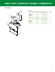

NOTES:
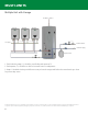
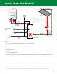
1. Ensure field supplied tank aquastat is in top 1/3 section of the tank.
2. Set tank aquastat 10°F lower than tankless unit set point.
3. Ensure the hot water return from the tankless unit is connected to the hot water outlet from the solar tank as
shown in the drawing.
4. The supply line to the tankless unit may be made at the element fitting (after element is removed) with a 1”-11
1/2 NPSH fitting and gasket.
5. Field supplied pump must provide > 3 GPM flow through tankless backup loop - contact pump manufacturer for
sizing assistance.
AQUASTAT
SOLAR
COLLECTOR
COLD
WATER
INLET
SOLAR
CONTROL
COLLECTOR SENSOR
TANK SENSOR
GAS
SUPPLY
TEMPERED
HOT WATER
STORAGE TANK
T
CH
TANKLESS
WATER HEATER
HOT WATER
RETURN
FIELD SUPPLIED
PUMP
TANKLESS SUPPLY
LINE
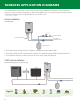
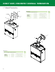
All application diagrams shown are concept drawings only. These diagrams are only to be used as basic guides. It is up to the application designer to properly design the plumbing layout and cor-
rectly size all components within an application (pumps, piping, storage tanks, water heaters, etc.). All national and local codes must be followed and will dictate proper compliance.
SOLAR TANKLESS BACK UP
44