On-Demand Water Heater Installation Manual and Owner’s Guide ANSI Z21.10.3・CSA 4.3 Models 240HX3 340HX3 540HX3 Gas Tankless Water HeaterTM If the information in these instructions is not followed exactly, a fire or explosion may result causing property damage, WARNING personal injury or death. - Do not store or use gasoline or other flammable vapors and liquids in the vicinity of this or any other appliance. - WHAT TO DO IF YOU SMELL GAS • Do not try to light any appliance.
Contents CONTENTS Installation Manual SPECIFICATIONS..............................................4 INTRODUCTION..............................................5 SAFETY GUIDELINES.....................................6 SAFETY DEFINITION.....................................6 GENERAL.......................................................6 INSTALLATION.................................................7 CLEARANCES................................................9 INCLUDED ACCESSORIES.............................
Installation Manual Installation Manual CONGRATULATIONS Congratulations and thank you for choosing our tankless water heater. Before use, we recommend that you read through this installation manual carefully. Keep this manual for future reference. If you need an additional manual, contact the manufacturer or your local distributor. You may also download a manual from our website.
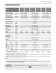
Installation Manual Specifications SPECIFICATIONS 240HX3 Indoor Model (AT-H3J-DVSCM) 240HX3 Outdoor (AT-H3J-OSSCM) 340HX3 Indoor (AT-H3S-DVSCM) 340HX3 Outdoor (AT-H3S-OSSCM) 540HX3 Indoor (AT-H3-DVSCM) 540HX3 Outdoor (AT-H3-OSSCM) Natural Gas Input (Operating Range) BTU/h Min.: 15,000 Max.: 160,000 Min.: 15,000 Max.: 180,000 Min.: 15,000 Max.: 199,000 Propane Input (Operating Range) BTU/h Min.: 13,000 Max.: 160,000 Min.: 13,000 Max.: 180,000 Min.: 13,000 Max.
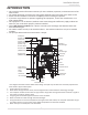
Installation Manual Introduction INTRODUCTION • This manual provides information necessary for the installation, operation, and maintenance of the water heater. • The model description is listed on the rating plate attached to the side panel of the water heater. • Please read all installation instructions completely before installing this product. • If you have any problems or questions regarding this equipment, consult the manufacturer or its local representative.
Installation Manual Safety Guidelines SAFETY GUIDELINES SAFETY DEFINITION DANGER WARNING CAUTION NOTICE Indicates an imminently hazardous situation which, if not avoided, will result in death or serious injury. Indicates an imminently hazardous situation which, if not avoided, could result in death or serious injury. Indicates an imminently hazardous situation which, if not avoided, could result in minor or moderate injury. Indicates information considered important but not hazard related.
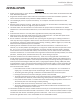
INSTALLATION Installation Manual Installation GENERAL 1. Follow all local codes, or in the absence of local codes, follow the current edition of the National Fuel Gas Code: ANSI Z223.1/NFPA 54. 2. All gas water heaters require careful and correct installation to ensure safe and efficient operation. This manual must be followed exactly. Read the "Safety Guidelines" Section. 3. The manifold gas pressure is preset at the factory. It is computer controlled and should not need adjustment. 4.
Installation Manual Installation • Installation and service must be performed by a qualified installer (for example, a licensed plumber or gas fitter). Otherwise, the warranty will be void. • The installer (licensed professional) is responsible for the correct installation of the water heater and for compliance with all national, state/provincial, and local codes. • The manufacturer does not recommend installing the water heater in a pit or location where WARNING gas and water can accumulate.
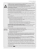
Installation Manual Installation CLEARANCES WARNING Maintain all clearances around the water heater. Failure to do so could create a fire hazard, potentially leading to death, serious injury, and/or property damage. Model Top Bottom Front Back Sides Indoor 12 in (305 mm) 18 in (458 mm) 4 in* (102 mm) 0.5 in (13 mm) 3 in (76 mm) Top Side Back Front Outdoor 36 in (914 mm) 18 in (458 mm) 24 in (610 mm) 0.5 in (13 mm) Side 3 in (76 mm) *24 inches (610 mm) recommended for maintenance.
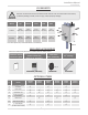
Installation Manual Installation 1. Temperature remote controller: 100209924 (TM-RE42) The temperature remote controllers have three functions. It allows the output temperature from the water heater to be adjusted and it also works as a diagnostic tool and it provides a concise error code whenever there is a problem with the unit. See the Troubleshooting Section (pages 53 to 55) for information on possible error codes. 2.
WARNING FOR INSTALLATIONS Installation Manual Installation FOR YOUR SAFETY, READ BEFORE INSTALLATION: Do not install the heater where water, debris or flammable vapors may get into the flue terminal. This may cause damage to the heater and void the warranty. Do not have the vent terminal pointing toward any opening into a building. Do not locate your heater vent terminal, and air intake in a pit or location where gas and water can accumulate.
Installation Manual Installation HIGH-ALTITUDE INSTALLATIONS • • WARNING • Adjust the appropriate DIP switches according to model and elevation as shown below. DO NOT adjust the other DIP switches. Turn off the power supply to the water heater before changing the DIP switch settings. Failure to observe these warnings could lead to carbon monoxide poisoning or death.
Installation Manual Installation VENTING INSTRUCTIONS WARNING • Improper venting of this appliance can result in excessive levels of carbon monoxide which can result in severe personal injury or death. • Improper installation can cause nausea or asphyxiation, severe injury or death from carbon monoxide and flue gases poisoning. Improper installation will void product warranty. • When installing the vent system, all applicable national and local codes must be followed.
Installation Manual Installation -Vent termination clearancesInside corner detail Legend: V = Vent terminal X = Air supply inlet = Area where terminal is not permi�ed G V D L H A E B B C Fixed closed Operable V F V B 15 � B Fixed Operable closed V B V M V J A X V X K I Regulator vent outlet In the event no regulator is present, H and I can be disregarded B US Installations1 A Clearance above grade, veranda, porch, deck, or balcony K Clearance to mechanical air supply inlet
Installation Manual Installation -Clearances for sidewall terminationsImproper installation can result in carbon monoxide poisoning or death. Follow all local and national codes in regards to proper termination clearances. In the absence of such codes, the clearances below can be used as guidelines. Local codes supersede these guidelines. WARNING Exhaust Termination Multiple Sidewall Terminations An exhaust termination must be at least 1 ft (305 mm) away from another exhaust termination.
Installation Manual Installation -Clearances for rooftop terminationsFollow all local and national codes in regards to proper termination clearances. In the absence of such codes, the clearances below must be met. Local codes supersede these clearances. Failure to observe this warning may result in severe personal injury or death. WARNING Angled roof termination 2 ft (610 mm) min. Exhaust Intake 1 ft (305 mm) min. Intake 1 ft (305 mm) min.
Installation Manual Installation -Combustion air supplyThis gas water heater requires an adequate source of clean air for combustion and ventilation. Without sufficient air, your water heater may not operate properly and may emit excessive and abnormal amounts of carbon monoxide which may result in WARNING carbon monoxide poisoning or death. NOTICE The guidelines in this section apply to installations within the United States. All U.S. installations must conform to the National Fuel Gas Code, ANSI Z223.
Installation Manual Installation Your water heater’s BTU/h rating is on the rating plate. The BTU/h ratings should be on the other appliances’ rating plates. If you have trouble determining the BTU/h ratings, contact the manufacturer or have a qualified person determine the ventilation requirements. NOTICE: If you are replacing your old water heater with one that has a higher BTU/h rating, the amount of ventilation required may be greater.
Installation Manual Installation Determine type of ventilation There are several types of ventilation that can be used. The various options are listed below. See also the illustrations on the next page. 1. 2. 3. 4. Direct to outdoors Vertical ducts Horizontal ducts-Single opening (not recommended; must be at least 100 in2 (645 cm2) . Not appropriate for confined spaces smaller than 50 ft3 (1.42 m3) per 1,000 BTU/h or when getting air from another room.
Installation Manual Installation Combustion air supply options X3™ CARTRIDGE NOT SHOWN FOR CLARITY. Gable vent to outdoors Install above insulation 12” (305 mm) maximum Outlet air to attic 1 in2 (6.5 cm2) per 4,000 btu/h Confined Space Two permanent Openings Alternate Air Inlet Inlet air from the crawl space 1 in2 (6.5 cm2) per 4,000 btu/h 1 in2 (6.
Installation Manual Installation -Exhaust vent (ABS, PVC, CPVC, or polypropylene vent)The indoor models can be vented with schedule 40 PVC (temperature rated up to 149 °F), CPVC, ABS, or polypropylene.
Installation Manual Installation -DIP switch settings for vent length- Typical installations using PVC, CPVC, ABS, or polypropylene vent • Adjust the appropriate DIP switches according to model and vent length as shown below. DO NOT adjust the other DIP switches. Turn off the power supply to the water heater before changing the DIP switch settings. Failure to observe these warnings could lead to carbon monoxide poisoning or death. • WARNING • 3 inch & 4 inch vent installation X3™ CARTRIDGE NOT SHOWN.
Installation Manual Installation • Adjust the appropriate DIP switches according to model and vent length as shown in the following. DO NOT adjust the other DIP switches. Turn off the power supply to the water heater before changing the DIP switch settings. Failure to observe these warnings could lead to carbon monoxide poisoning or death.
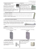
Installation Manual Installation 4" vent connection for PVC/CPVC venting only 4" straight pipe 4" straight pipe 4"straight pipe 3" x 4" increaser 3" x 4" increaser 3" x 4" increaser 3"straight pipe no more than 12" (305 mm) 3" straight pipe no more than 12" (305 mm) Exhaust vent collar with 3" adapter* (Female) Intake vent collar with 3" adapter* (Female) 1. Insert no more than 12" (305 mm) of 3" straight pipe into the exhaust/intake vent collar with 3" adapter. 2.
Installation Manual Installation -Exhaust vent (Stainless steel vent)This is a Category IV appliance and must be vented accordingly. The vent system must be sealed airtight. All seams and joints without gaskets must be sealed with high heat resistant silicone sealant or UL listed aluminum adhesive tape having a minimum temperature rating of 160 °F (71 °C). For best results, a vent system should be as short and straight as possible.
Installation Manual Installation DIP switch settings : Single pipe and Direct vent installations / Vent diameter : 4" venting 240HX3/340HX3 Indoor 540HX3 Indoor (Upper bank of DIP switches) Vent length 5 to 50 ft (1.5 to 15.2 m) (DEFAULT) 51 to 100 ft (15.3 to 30.5 m) 5 to 50 ft (1.5 to 15.2 m) (DEFAULT) 51 to 100 ft (15.3 to 30.5 m) ON 1 2 3 4 5 6 7 8 9 10 ON 1 2 3 4 5 6 7 8 9 10 ON 1 2 3 4 5 6 7 8 ON 1 2 3 4 5 6 7 8 OFF OFF OFF OFF No. 6 : O N No. 7 : OFF No. 6 : OFF No. 7 : OFF No.
Installation Manual Installation Approved Category IV, Single Wall, Venting Suppliers and Part Numbers Z-FLEX® Description Heater Vent Kits 4" Adjustable straight pipe - 10"-18" (254 - 457 mm) adjustability 100112405 2NVAL4 2SVSPA04 4" Sidewall termination (4" Termination Hood) 100112419 2NVTH4 2SVSHTX04 4" Vent termination tee 100112547 2NVTT4 2SVSTTF04 4" Rain Cap 100112415 2NVRC4 2SVSRCF04 4" Extreme weather rain cap 100112548 2NVWC4 2SVSHRC04 4" 3-in-1 adaptor (F-F adaptor, conden
Installation Manual Installation -Common-venting system- The Indoor model can be vented together using the same exhaust and intake venting except 140H model. • The 240HX3/340HX3/540HX3 models do not have Easy-Link or Multi-Unit capability. • Up to 8 water heaters can be common-vented together. • A non-return valve (100113130) must be used for each water heater that is part of the system. • The water heaters must all be direct-vented.
Installation Manual Installation To determine the dimension of a common-venting system Determine the vent diameter (D) and the total vent length based on the number of water heaters installed. The total vent length (L) consists of the horizontal width (W) and the vertical height (H). See the table below.
Installation Manual Installation GAS SUPPLY AND GAS PIPE SIZING -General• Do not use this water heater with any gas other than the one listed on the rating plate. • Ensure that any and all gas regulators used are operating properly and providing gas pressures within the specified range shown below. Excess gas inlet pressure may cause serious accidents. WARNING • Conversion of this unit from natural gas to propane or vice versa will void all warranty.
Installation Manual Installation -Natural gas supply piping- Maximum delivery Capacity in Cubic Feet of Gas per Hour (based on IPS Pipe carrying Natural Gas with 0.60 Specific Gravity with a Pressure Drop of 0.5" W.C.). Based on Energy Content of 1,000 BTU/Cubic ft: The water heater requires 160 Cubic ft/hr for the 240HX3 model, 180 Cubic ft/hr for the 340HX3 model, and 199 Cubic ft/hr for the 540HX3 model. The following tables are from NFPA 54.
WATER CONNECTIONS WARNING Installation Manual Installation Do not use this appliance if any part has been under water. Immediately contact a qualified installer or service agency to replace a flooded water heater. Do not attempt to repair the unit! It must be replaced! Do not reverse the hot outlet and cold inlet connections to the water heater. This will prevent the water heater from activating properly.
Installation Manual Installation -X3™ Scale Prevention Technology- This water heater is equipped with X3™ Scale Prevention Technology to inhibit scale formation within the heat exchanger tubing of this unit. Part of the X3™ Technology’s anti-scale protection comes from the special X3™ Cartridge media. The X3™ Cartridge must be installed into the manifold located on the underside of the heater cabinet prior to operation of the unit (shown as follows).
Installation Manual Installation CONDENSATE DRAIN This high efficiency water heater produces acidic condensate that must be properly drained per local codes. The water heater does not have a built-in neutralizer to raise the pH level. A neutralizer is available from the water heater manufacturer, if needed. Follow the instructions in this section in order to install the condensate drain line. • All preventative measures and safety practices must be adhered to when draining condensate.
Installation Manual Installation Installation without neutralizer Installation with neutralizer X3™ CARTRIDGE NOT SHOWN FOR CLARITY.
Installation Manual Installation ELECTRICAL CONNECTIONS • • WARNING • • Ensure that circuit power is turned OFF before you complete the following steps. Follow the electrical code requirements of the local authority having jurisdiction. In the absence of such requirements, follow the current edition of the National Electrical Code ANSI/NFPA 70. When servicing or replacing parts within the water heater, label all wires prior to disconnection to facilitate an easy and error-free reconnection.
Installation Manual Installation TEMPERATURE REMOTE CONTROLLER • • -Included accessories-Outdoor models only The remote control is an optional accessory that can be installed in a hall, closet, etc., to allow for temperature adjustment without having to go to the heater. When installed, the remote will take priority over the built-in controller of indoor models. Verify that the items listed below are included with the remote controller.
Installation Manual Installation 4. Tighten the two Fork terminals beneath the two Remote controller terminal screws on the back of the main body. (Fig. D-1) 5. Cut out the inlet for the remote controller cable from the bottom of the main body. (Fig. D-2) 6. Place the Main body back on the Back plate, with the Remote controller cable running out of the bottom inlet. Fig. D-1 Remote controller terminals Fig.
Installation Manual Applications APPLICATIONS -Standard single unit piping configulation- Below is a suggested piping diagram. This diagram is just a suggestion. Check with local codes and ordinances for additional installation requirements. Refer to the water heater manufacturer’s website for additional layouts. Thermostatic mixing valves may be used with tankless water heaters. Consult with the mixing valve manufacturer for the appropriate mixing valve for the application.
Installation Manual Initial operation INITIAL OPERATION FOR YOUR SAFETY, READ BEFORE OPERATING • Check the GAS and WATER CONNECTIONS for leaks before firing unit for the first time. • Open the main gas supply valve to the unit using only your hand to avoid any spark. Never use tools. If the knob will not turn by hand, do not try to force it; call a qualified service technician. Forced repair may result in a fire or explosion due to gas leaks.
Owner's Guide Owner's Guide CONGRATULATIONS Congratulations and thank you for choosing our tankless water heater. Before use, we recommend that you read through this owner's guide carefully. Keep this manual for future reference. If you need an additional manual, contact the manufacturer or your local distributor. You may also download a manual from our website. When you call, please tell us the product name and the serial number of your unit written on the rating plate of the water heater.
Owner's Guide Operating Safety OPERATING SAFETY FOR YOUR SAFETY READ BEFORE OPERATING WARNING: If you do not follow these instructions exactly, a fire or explosion may result causing property damage, personal injury or loss of life. A. This appliance does not have a pilot. It is equipped with an ignition device which automatically lights the burner. Do not try to light the burner by hand. B. BEFORE OPERATING smell all around the appliance area for gas.
Owner's Guide Operating Safety DANGER Vapors from flammable liquids will explode and catch fire causing death or severe burns. Do not use or store flammable products such as gasoline, solvents or adhesives in the same room or area near the water heater. Flammable Vapors FLAMMABLES Do not install water heater where flammable products will be stored or used unless the main burner is at least 18” above the floor. This will reduce, but not eliminate the risk of vapors being ignited by the main burner.
Owner's Guide Normal Operation NORMAL OPERATION BUILT-IN CONTROLLER AND REMOTE CONTROLLER The illustration below shows an example of the controllers. The exact display may differ from examples. Built-in controller Display for Temperature When the STAND BY LED is ON, the hot water temperature will be displayed. Remote controller "INFO" Button Each time the button is pressed, the operation mode is selected in the sequence of the following.
Owner's Guide Normal Operation OUTLET WATER TEMPERATURE SETTING -Set temperatureScreen on the controller Operation Built-in controller 1. Turn on the 120 VAC power supply to the unit (the water heater or the multi-unit controller). 2. Press the "ON/OFF" button on the controller in order to turn the controller on. 3. When ON, the STAND BY LED is lit. 4. It shows the set temperature on its display as shown in the picture on the right. (EX.: 120 °F) (EX.
Owner's Guide Normal Operation ADDITIONAL FEATURES -Information mode- You can get some information about the water heater condition by pressing the "INFO" button. For more information, follow the procedures below: INFO Button 1st. press 2nd. press 3rd. press 4th. press Screen on the controller Operation Built-in controller Inlet water temperature will be displayed on the controller by pressing the "INFO" button.
Owner's Guide Normal Operation TEMPERATURE SETTINGS ON THE PCB (WITHOUT REMOTE CONTROLLER) • Adjust the appropriate DIP switches according to model and temperature as shown below. DO NOT adjust the other DIP switches. Turn off the power supply to the water heater before changing the DIP switch settings. Failure to observe these warnings could lead to carbon monoxide poisoning, severe personal injury, or death.
Owner's Guide Normal Operation FREEZE PROTECTION SYSTEM • This water heater comes equipped with heating blocks to protect it from damage associated with freezing. When the freeze protection thermostat senses air temperature below 36.5 °F (2.5 °C), the blocks will heat up to prevent freezing of the unit. • The 540HX3 Indoor model briefly fires on for about 3 seconds to provide freeze protection around the heat exchanger drum - Automatic firing system.
MAINTENANCE AND SERVICE • WARNING • Owner's Guide Maintenance and service Turn off the electrical power supply and close the manual gas shutoff valve and the manual water control valve before servicing. Failure to do so could result in severe personal injury, or death. The following maintenance is required for the proper operation of water heaters. • Regularly ensure that the area around the water heater, vent termination, and air intake are free from dust, debris, and other contaminants.
Owner's Guide Maintenance and service UNIT DRAINING & POWER OUTAGE (FREEZE PROTECTION) If you will not be using your heater for a long period of time, drain the water out of the unit completely and disconnect power to your heater to keep the water heater from freezing and being damaged. 1. Close the manual gas shutoff valve. 2. Turn off power to the unit and wait five (5) seconds. Turn on again. Drain plug with Filter (Large) 3. Wait 30 seconds, and then turn off power to the unit. 4.
Owner's Guide Maintenance and service MEASURING INLET GAS PRESSURE 1. Turn off all electric power to the water heater if service is to be performed. 2. Turn the manual gas valve located on the outside of the unit to the off position. 3. Failure to follow these steps could lead to fire or explosion, resulting in personal injury or death. WARNING The water heater cannot perform properly without sufficient inlet gas pressure. Below are instructions on how to check the inlet gas pressure.
Owner's Guide Troubleshooting TROUBLESHOOTING PROBLEM SOLUTIONS TEMPERATURE and AMOUNT OF HOT WATER It takes a long time to • The time it takes to deliver hot water from the water heater to your fixtures get hot water at the depends on the length of piping between the two. The longer the distance or fixtures. the bigger the pipes, the longer it will take to get hot water. The water is not hot enough. The water is too hot. The hot water is not available when a fixture is opened.
Owner's Guide Troubleshooting BUILT-IN CONTROLLER AND REMOTE CONTROLLER PROBLEM Controller does not display anything when the power button is turned on. SOLUTIONS • Make sure the unit is supplied with power. • Make sure the connection to the unit is correct. (pp. 37 and 38) NOTICE: When the unit has not operated for five minutes or more, the display of the controllers turns off to conserve energy. When the controller turned ON, STAND BY LED is lit. Built-in controller An ERROR code is displayed.
Owner's Guide Troubleshooting Error Indication Error Code on the temperature controller The number of flashes 031 701 711 One 311 321 331 341 391 Two 111 121 Three 611 661 Four 101 291 941 991 Five 510 551 721 Six Green LED Flash pa�ern on off on off 0.5 sec. on, 0.5 sec. off 3 sec. off -Fault Analysis of Error CodesIf the error code is displayed on the computer board of the water heater or remote controller and/or temperature controller, please check the following.
Owner's Guide Troubleshooting Controller 311* 321* 331* 341* 391* 510 551 Green LED Malfunction description Diagnosis Two 240HX3/340HX3: Flashes Outlet Thermistor Failure 540HX3: Heat Exchanger Thermistor Failure • Check for connection/breakage of wires and/or debris on thermistor (Part Two Inlet thermistor failure #407, 408, 411, 715, 718, 721).
Owner's Guide Components Diagram COMPONENTS DIAGRAM Case assembly 419 Indoor Outdoor 052 052 003 007 004 067 713 052 001 004 717 002 001 702 704 006 702 008 005 052 704 050 052 002 050 Built-in controller Indoor 723 Surge box assembly 056 121 703 722 713 Temperature remote controller 703 706 724 56 Page 053 713 704
Owner's Guide Components Diagram Computer board assembly 701 240HX3/340HX3 709 540HX3 711 708 713 708 714 714 103 721 709 716 711 701 713 715 103 402 716 402 402 408 407 061 707 402 722 715 707 722 721 715 Wiring diagram R SV2 O 240HX3/340HX3 SV3 711 LB BL MV O.H.C.
Owner's Guide Components Diagram Burner assembly Burner assembly 101 104 115 053 053 709 108 107 401 106 116 053 110 062 109 111 711 Manifold assembly 102 112 117 053 114 105 113 063 065 708 121 054 150 711 103 709 119 G 707 062 151 057 055 055 117 063 540HX3 051 066 719 118 714 58 Page
Owner's Guide Components Diagram Water Way assembly 418 413 453 452 403 456 F 412 458 419 058 460 A 462 B 472 458 Bypass section 540HX3 462 473 064 418 468 471 E 462 458 E 053 F 458 451 A 415 462 476 462 458 451 414 414 455 C 463 423 463 477 068 C 458 052 469 052 474 454 408 456 460 402 461 417 409 725 009 462 052 450 416 G 455 D 458 414 464 461 458 422 465 475 540HX3 422 414 240HX3/340HX3 454 411 421 458 451 459 401 451 466 458 470
Owner's Guide Parts list PARTS LIST N/A: Part with no part number assignment Item # 001 002 003 004 005 006 007 008 009 050 051 052 053 054 055 056 057 058 059 060 061 062 063 064 065 066 067 068 101 102 103 104 105 106 107 108 109 110 111 112 112 113 114 115 Model Description 240HX3 Case assembly Indoor Case assembly Outdoor Front cover Indoor Front cover Outdoor Intake air port assembly Bracket Junction box Power supply cord assembly Back guard panel Chamber fixing plate Condensate drain port Truss
Owner's Guide Parts list Item # 116 117 118 119 121 150 151 152 153 401 402 403 404 405 406 407 408 409 410 411 412 413 414 415 415 416 417 418 419 420 421 422 423 450 451 452 453 454 455 456 457 458 459 460 461 462 463 464 465 466 467 468 469 470 471 472 473 Model Description 240HX3 Pressure port Combustion chamber tube Gas inlet Gas inlet ring Surge box plate O-ring P18 NBR (Black) O-ring P20 NBR (Black) Silicon ring for Outdoor models Exhaust port for Outdoor models Primary heat exchanger assembly Fl
Owner's Guide Parts list Item # 474 475 476 477 701 702 703 704 706 707 708 709 711 713 714 715 716 717 718 719 721 722 723 724 725 Model Description 240HX3 X3™ Inlet pipe X3™ Outlet pipe X3™ pipe joint X3™ Manifold assembly Computer board Rubber grommet Surge box 120 VAC wire for Indoor model 120 VAC wire for Outdoor model 120 VAC Power ON-OFF switch Remote controller wire Gas valve wire Flame rod wire Igniter assembly Switch wire with thermostat for Indoor model Switch wire with thermostat for Outdoor
Owner's Guide Output Temperature Chart OUTPUT TEMPERATURE CHART These charts are based on properly sized gas lines and installation at 0-2,000 ft (0-610 m). The water heater will de-rate approximately 4% per 1,000 ft (305 m) of elevation increase above 2,000 ft (914 m). To reduce the risk of scalding, install Thermostatic Mixing Valves (temperature limiting valves) at each point of use. Output Temperature vs. GPM (Max. 6.
3PL009 2000599585 (Rev.