
Water Heater Installation Manual


13 Page
Installaon
Installaon Manual
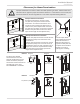
VENTING INSTRUCTIONS
• Improper venting of this appliance can result in excessive levels of carbon monoxide which
can result in severe personal injury or death.
• Improper installation can cause nausea or asphyxiation, severe injury or death from carbon
monoxide and flue gases poisoning. Improper installation will void product warranty.
• When installing the vent system, all applicable national and local codes must be followed.
If you install thimbles, fire stops or other protective devices and they penetrate any
combustible or noncombustible construction, be sure to follow all applicable national and
local codes.
WARNING
The Indoor model must be vented in accordance with "Venting of Equipment" in the current edition of the
National Fuel Gas Code: ANSI Z223.1/NFPA 54 as well as applicable local building codes.
The use of venting materials approved for Category III/IV appliances is required. In addition, PVC (solid core),
CPVC, ABS, and polypropylene are approved for use with the indoor models. For details, please refer to the
Exhaust Vent (ABS, PVC, CPVC, or Polypropylene Vent) Section on pages 21 to 24.
General rules for venting water heaters:
• Place the water heater as close as possible to the vent termination.
• The vent collar of the water heater must be fastened directly to an unobstructed vent pipe.
• Do not weld the vent pipe to the water heater’s vent collar.
• Do not cut or alter the vent collar of the unit.
• The vent must be easily removable from the top of the water heater for normal service and inspection of
the unit.
• The water heater vent must not be connected to any other gas appliance or vent stack except an approved
common-venting system. Refer to pages 28 and 29.
• Avoid using an oversized vent pipe or using extremely long runs of the pipe unless it is part of an approved
common vent system.
• Air supply pipe can be made of ABS, PVC (solid core), CPVC (solid core), polypropylene, corrugated stainless
steel, or Category lll/IV stainless steel. Regarding exhaust pipe, refer to pages 21 to 27.
• Use of cellular core PVC (ASTM F891), cellular core CPVC, or Radel® (polyphenylsulfone) in nonmetallic
venting systems is prohibited. Covering non-metallic vent pipe and fittings with thermal insulation is
prohibited.
• Sidewall venting is recommended for the Indoor model. Vertical venting (roof termination) is acceptable.
• Slope horizontal venting sections 1/4" upwards for every 12" (300 mm) toward the termination or
according to local and state codes, or in the absence of local or state codes, the current edition of the
National Fuel Gas Code, ANSI Z223.1 (NFPA 54)
• The manufacturer recommends running the exhaust vent and the intake pipe as parallel as possible.
• For rooftop venting, a rain cap or other form of termination that prevents rain water from entering into the
water heater must be installed.
• Do not terminate vent into a chimney. If the vent must go through the chimney, the vent must run all the
way through the chimney with approved vent pipe.
• The water heater shall not be connected to a chimney flue serving a separate appliance, designed to burn
solid fuel.
• When an existing Category I appliance is removed or replaced, the original venting system may no longer
be sized to properly vent the attached water heater. An improperly sized venting system may cause
formation of condensate, leakage, and spillage and so on. Follow all instructions in this manual.
General rules for vent terminations:
• Avoid locating the water heater vent termination near any air intake devices. These fans can pick up the
exhaust flue products from the water heater and return them to the building. This can create a health
hazard.
• Locate the vent termination so that it cannot be blocked by any debris, at any time. Most codes require
that the termination be at least 12 in (305 mm) above grade and anticipated snow level, but the installer
may determine if it should be higher depending on the job site condition and applicable codes.
• A proper sidewall termination is recommended when the water heater is vented through a sidewall.
• Regarding the clearances from the exhaust termination to the air inlet or opening, refer to pages 14 to 16.