
Operating Instructions and Installation Instructions

Instruction manual BFM 35
is
3.10 Electrical
connection
Warning
The installation should be carried out by an authorised installation engineer,
in compliance with general and local regulations (1.3 "Regulations").
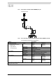
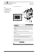
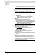
This paragraph describes the electrical connections.
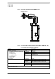
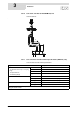
The figure shows a view of the electrical connector block, and the table shows
the appropriate connections.
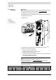
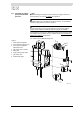
Connector block
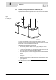
In preparation you should first remove the two plastic covers and the
protective cap of the electrical section.
1. Undo the screws of the plastic covers.
2. Carefully remove the covers from the appliance.
The electrical section is now visible.
3. Loosen the 2 screws (A) of the electrical section, and remove the protective
cover (B) from the electrical section.
The connector block (C) is now visible.
Note
Refer to the table for connections 1 through 10.
Consult the electrical diagram (14 "
Electrical diagram") for the electrical
component connections.
Electrical connector block
Legend
A. screws
B. protective cap
C. connector block
A
B
C
1
10
IMD-0243 R1
Mains power Fan Alarm Off
NL1 NL S1S2S3S4
123 45 6 7 8 910