
Operating Instructions and Installation Instructions


Conversion to a different gas category
42 Instruction manual BFM
4
is
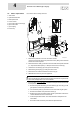
4.2 Orifice replacement
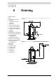
Gas control valve assembly removed
1. Remove the protective cover from the control column:
undo the 4 screws and remove the protective cover by lifting it. The electrical
section will now be exposed.
2. Remove the strain relief (1) and disconnect the leads of the spark electrode
(2 = red) and the flame probe (3 = black) from the burner control (4).
3. Unscrew the connector(s) (5) of the gas control valve (6).
4. Remove the gas coupling (7) of the gas control valve.
5. Remove the ten screws that fasten the burner tray (8).
6. Withdraw the burner tray from the appliance.
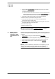
Note
When exchanging the pilot flame orifice and/or main orifices: Lay the burner
tray on its side and approach it from the underside.
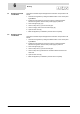
7. If the gas table (3.4.3 "
Gas data") indicates that the pilot flame orifice needs
to be replaced:
a. Remove the spark electrode (1) from its retaining clip. This way you will
gain space to remove the pilot flame orifice.
b. Turn the flame probe (2) and remove it from its bracket to gain space.
c. Remove the bracket of the pilot flame orifice (3).
d. Replace the current pilot flame orifice (4) with a pilot flame orifice of the
correct diameter from the conversion set.
e. Check the pilot flame orifice. The orifice diameter is stamped on the
orifice itself..
f. Re-fit the bracket, the flame probe and the spark electrode.
1. strain relief
2. spark electrode lead
3. flame probe lead
4. burner control
5. gas control valve connector(s)
6. gas control valve
7. gas coupling
8. burner tray
1
2
4
5
6
7
5
5
8
6
7
3
IMD-0254 R1