EQ 115 EQ 155 EQH 200 United Kingdom & Ireland HOT WATER STORAGE HEATERS 0311918 4115 - Reserved Changes.
Read these installation instructions first before installing the appliance. Carefully read the user instructions before igniting the appliance. Failure to follow these instructions may lead to risk of explosion and/or fire and could cause material damage and/or bodily harm. Installation and commissioning should be carried out by a qualified competent installer. The type of gas and the value at which the appliance is set standard in the factory are registered on the rating plate.
CONTENTS PAGE 1. 1.1 1.2 1.3 1.4 1.4.1 1.4.2 1.5 1.5.1 1.6 General....................................................................................................................4 Description of the appliance.....................................................................................4 Packaging material...................................................................................................4 Disposal...................................................................................
1. GENERAL 1.1 Description of the appliance Construction of the water heater is in accordance with the European standard for gas heated water storage heaters for sanitary application (EN 89). The appliance thus meets the European Directory for Gas Appliances and is therefore entitled to carry the CEmarking. It is an open flued appliance without ventilator and with a flue gas down draught safeguard (category B11BS). The water heater is suitable for a maximum working pressure of 8 bar.
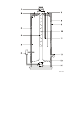
AOS 0478 Figure 1 - Cross-section of the heater 1) Draught diverter - Cross-section of the heater 2)Figure Hot1 water outlet 3) Insulation 4) Flue tube 5) Glass lined tank 6) Gas control valve 7) Cold-water inlet diverter 8)1) Draught T&P valve connection 2) Hot water outlet 3) Insulation 4) Flue tube 5) Glass lined tank 6) Gas control valve 7) Cold-water inlet 9) 10) 11) 12) 13) 14) 8) 9) 10) 11) 12) 13) 14) Outer casting Flue baffle Sacrificial anode Drain valve Atmospheric burner Pilot light burner wi
1.4 Technical safety equipment 1.4.1 Gas control valve The water heater has been fitted with a gas control block consisting of a thermo-electrical pilot flame safeguard, pilot flame pressure regulator, burner pressure regulator, a control thermostat (adjustable between 30°C and 71°C) and a safety thermostat (82°C). This gas control block with its simple and secure control respectively switches the gas supply to the main burner on or off.
AOS 0479 Figure 2 - Gas control block with T.R.S. 1) T.R.S. thermostat 2) Sensor combustion products safety device Figuredicharge 2 - Gas control block with T.R.S 3) Thermocouple with built-in interrupter 4) 5) 6) 7) 8) Thermocouple Gas control block Reset button Pilot burner Temperature regulator knob 1) T.R.S.
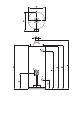
1.5 Technical description 1.5.1 Dimensions These water heaters are only suitable for a flue tube with minimal the announced diameter (dimension G).
Figure 3 - Dimensions 9
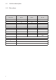
1.6 Technical data Device category: II2H3+ DESCRIPTION unit EQ 115 EQ 155 EQH 200 Nominal load (gross) kW 9.3 11.3 18.3 Nominal capacity kW 7.4 9.0 14.0 Suppy pressure mbar 20 20 20 Burner pressure mbar 12.5 12.5 10.5 Gas consumption * m3/h 0.9 1.1 1.7 Diameter main orifice mm 2.35 2.60 3.50 Diameter pilot orifice mm 2 x 0.27 2 x 0.27 2 x 0.27 Heating time ΔT= 44 K min.
DESCRIPTION unit EQ 115 EQ 155 EQH 200 Load Profile - L XL XXL Energy Efficiency Class (Energy Label) - B B B Energy Efficiency % 61 68 61 Daily Electricity Consumption kWh 0.000 0.000 0.000 Daily Fuel Consumption kWh GCV 21.370 30.653 40.513 Mixed Water 40°C (V40) ltr. 172 250 346 Additional Load Profile - - - - Energy Efficiency % - - - Daily Electricity Consumption kWh - - - Daily Fuel Consumption kWh GCV - - - Mixed Water 40°C (V40) ltr.
2. FOR THE INSTALLER 2.1 Installation instructions This water heater must be fitted in a location which will permit the provision of an approved flue system and adequate ventilation. A service clearance of 15 cm at the sides and rear of the unit and 60 cm at the front of the unit should be allowed for ease of servicing.
See Figure 4. A.O. Smith water heaters are tested to a maximum pressure of 12 bar and a maximum working pressure of 8 bar.
2.1.3 Gas connection The gas supply to this appliance must be installed in accordance with BS 6891 (1988). Fit the 1/2" gas supply cock supplied with this unit immediately before the gas control block. No heat or soldered joints should be applied in the vicinity of the gas control block, as they could cause damage to the control. All connections and joints should be tested for gas soundness with a suitable leak detector (do not use a naked flame). 2.1.
2.2 Commissioning 2.2.1 Filling the water heater 1. Close the drain tap. 2. Open the cold water tap to the water heater and open all taps where hot water can be drained for deaeration. The water heater is filled as soon as cold water flows from all taps. 3. Close all hot water taps. 2.2.2 Putting into operation 1. Check whether the water-heater has been filled with water and whether the gas supply to the water heater is open. 2.
2.2.3 Removing and replacing the inner door (only for the EQ 115/155 models, see Figure 7a). Procedure: 1. Place lip A through the recess on the right and subsequently slide it down behind the steel wall. See to it that both lower lips remain in front of the metal wall. 2. Press lip B through the recess on the left. 3. Subsequently slide lip B behind the steel wall (see Figure 7a). (only for the EQH 200 model, see Figure 7b). Procedure: 1. Turn down both clamps (1). 2.
recommended to also close the cold water tap and to drain the appliance after cooling (open the drain tap; it is possible to connect a drain hose to the drain tap; open the nearest hot water drain point to prevent air locks). To be able to drain the appliance completely it should be disconnected and tilted slightly in the direction of the drain tap. 2.5 Temperature regulation The appliance is under water supply pressure (maximum 8 bar).
2.6 Setting the nominal heat input The gas control has been factory preset to the water heater nominal heat input. A further check of the burner pressure should be carried out during the commissioning of the unit after installation. The following procedure should be followed. 1. Remove the protruding cover screw on the right side of the gas control block and connect a U-gauge manometer to the outlet. 2. Put the appliance into operation and ignite the burner. 3.
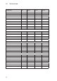
Description Unit EQ 115 EQ 155 G20 G30 G31 G20 G30 G31 Inlet pressure mbar 20 30 37 20 30 37 Burner pressure mbar 12.5 30 37 12.5 30 37 Diameter main injector mm 2.35 1.40 1.40 2.60 1.50 1.50 Diameter pilot injector mm 2x0.27 0.22 0.22 2x0.27 0.22 0.22 Description Unit EQH 200 G20 G30 G31 Inlet pressure mbar 20 30 37 Burner pressure mbar 10.5 30 37 Diameter main injector mm 3.50 1.95 1.95 Diameter pilot injector mm 2x0.27 0.22 0.
AOS 0487 Figure 10 - Conversion to another gas 4.b Conversion from LP-gas to natural gas: - Put the pressure regulator into operation. To do this the temperature regulating knob should be pulled straight forward. Next the red plastic cover that is now visible, should be removed. Turn the ‘no pr’ (no pressure regulation) screw completely up (see Figure 10). - Seal this setting with lacquer. - Remount the burner in reverse order. - Open the main gas tap. - Set the correct burner pressure (see table above).
2.8.2 Cleaning 1. Close the gas supply and demount the burner after it has cooled down, 2. Disconnect the burner, pilot pipe and thermo couple from the gas control block (see Figure 11), 3. Remove the complete burner assembly, 4. Clean the burner with a soft brush. 5. Check the pilot burner and clean it if so required, 6. Check the combustion chamber, flue tube and flue baffle and clean these if required, 7. Re-mount in reverse order.
2.10 Fault finding In case of failure the following should be checked. 2.10.1 Safety thermostat All appliances have been fitted with a safety thermostat that shuts off the gas supply when the water temperature is too high. The safety thermostat remains activated until the water temperature drops below the safety temperature. The water heater must be reignited manually. The regulation thermostat should be set to a lower water temperature.
3. FOR THE USER 3.1 Commissioning Warning Installing and commissioning (for the first time) of this water heater should only be carried out by a qualified competent heating engineer. 3.1.1 Filling the water heater 1. Close the drain tap. 2. Open the cold water tap to the water heater and open all taps where hot water can be drained for deaeration. The water heater is filled as soon as cold water flows from all taps. 3. Close all hot water drain taps. 3.1.2 Putting into operation 1.
and tilted slightly in the direction of the drain tap. 3.1.5 Maintenance The inlet combination has to be tested regularly by relieving it (via the relief button). The water has to flow out in a forceful jet. Check whether the discharge pipe is open. We recommend a service agreement on an annual basis. To be able to order spare parts it is important to note the type of appliance as well as the serial number of the appliance. Based on this information the data concerning the spare parts can be determined.
3.2 Fault finding Fault Possible cause Gas smell Pilot extinguishes Corrective action If you smell gas you should immediately close the main gas tap you should not light any fire or switch on light, electrical switches or bells. Open windows and immediately contact your installer or the local gas company. Blocked pilot burner Clean the pilot burner Blocked chimney Find the cause and remove it. Safety thermostat Set the temperature regulator at a lower temperature.
Fault Possible cause Corrective action Insufficient hot water, or none at all Safety thermostat has closed the gas supply because the water temperature was too high Set the temperature regulator at a lower temperature and reignite the pilot burner. Hot water storage empty Reduce the consumption of hot water. Allow the appliance time to heat the water. Cause cannot be determined Turn the control button to the () position. Close the gas tap and inform your installer.
4. GUARANTEE The following conditions form the guarantee agreement between A.O. Smith Water Products Company (the warrantor) and the owner of the water heater. 4.1 Guarantee in general If within one year of the original installation date of the water heater any part or component other than the tank shall prove upon examination by the warrantor or authorised agent to be defective in material or workmanship, the warrantor will exchange such part or component. 4.
any other dealer or stockist of the warrantors products. 4.7 No other guarantee or warranty either expressed or implied is made on behalf of A.O. Smith Water Products Company. With respect to the water heater in question further A.O. Smith does not guarantee this water heater as suitable for purpose except within the terms of warranty detailed above. A.O.
Important This form should be filled in completely within two weeks of installation. MODEL: ......................................................................................................................... SERIAL NUMBER: ......................................................................................................... ORIGINAL DATE OF INSTALLATION: ............................................................................ NAME OWNER: .....................................................
0311918 R0.
Uw Installateur Your Installer Ihr Installateur Votre Installateur Su Instalador Instalador Ditta Installatrice Twój Instalator Eγκαταστάτη Σας Nederland A.O. Smith Water Products Company B.V. Postbus 70 5500 AB VELDHOVEN United Kingdom A.O. Smith Water Heaters Unit B8 Armstrong Mall, Southwood Business Park, Farnborough, Hampshire, GU14 0NR 0800 - AOSMITH (2676484) info@aosmith.nl www.aosmith.nl 0870 - AOSMITH (267 6484) info@aosmith.nl www.aosmith.co.uk France A.O.