
Operation Manual


5
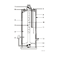
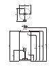
1) Draught diverter
2) Hot water outlet
3) Insulation
4) Flue tube
5) Glass lined tank
6) Gas control valve
7) Cold-water inlet
8) T&P valve connection
9) Outer casing
10) Flue bafe
11) Sacricial anode
12) Drain valve
13) Atmospheric burner
14) Pilot light burner with thermocouple
Figure 1 - Cross-section of the heater
5
Figure 1 - Cross-section of the heater
1) Draught diverter
2) Hot water outlet
3) Insulation
4) Flue tube
5) Glass lined tank
6) Gas control valve
7) Cold-water inlet
8) T&P valve connection
9) Outer casting
10) Flue baffle
11) Sacrificial anode
12) Drain valve
13) Atmospheric burner
14) Pilot light burner with thermocouple
AOS 0478