
Installation Guide

10
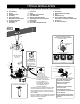
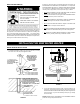
FIGURE 7.
4” (10.16 cm) MIN. - 30 GAL.
0” MIN. - 40 & 50 GAL.
0” MIN.
BASE DIAMETER
14” (35.56 cm) 30 GAL.
16” (40.64 cm) 40 GAL.
16” (40.64 cm) 50 GAL.
JACKET DIAMETER
18” (45.72 cm) 30 GAL.
20” (50.8 cm) 40 GAL.
22” (55.88 cm) 50 GAL.
30 GAL. T&P LOC.
40 & 50 GAL.
T&P LOC.
GAS CONTROL VALVE /
THERMOSTAT
AIR INTAKE
4” (10.2 cm) MIN.
2-1/2” (6.35cm)
4-13/32” (11.2 cm) - 30 GAL.
5-13/32” (13.7 cm) - 40 GAL.
5-13/32” (13.7 cm) - 50 GAL.
30 GALLON:
13-13/32” (34 cm) MIN.
40 GALLON:
15-13/32” (39.1 cm) MIN.
50 GALLON:
16-13/32” (41.7 cm) MIN.
9” (22.86 cm) MIN. - 30 GAL.
10” (25.4 cm) MIN. - 40 GAL.
11” (27.9 cm) MIN. - 50 GAL.
0” MIN.
9” (22.86 cm) MIN. - 30 GAL.
10” (25.4 cm) MIN. - 40 GAL.
11” (27.9 cm) MIN. - 50 GAL.
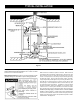
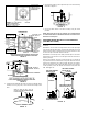
FIGURE 8.
2-7/32”
(5.59 cm)
GAS CONTROL VALVE / THERMOSTAT
4”
(10.16 cm)
BASE DIA. - 14”
(35.56 cm)
JACKET DIA. - 18”
(45.72 cm)
12-13/16”
(32.54 cm)
9”
(22.86 cm)
0” MIN.
0” MIN.
0” MIN.
3-13/16”
(9.68 cm)
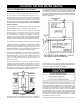
FIGURE 9.
3. Insert the duct assembly as shown in Figure 10 with lip facing
forward, and using only nails, secure the duct assembly to the
fl oor.
FRONT
APPLY 4” (10.16 cm) OR 5” (12.7 cm)
CIRCLE OF SILICONE AROUND OPENING
FOR AIR TIGHT SEAL.
FIGURE 10.
4. Set the water heater in place against the lip of the duct assembly
as shown in Figure 11.
FIGURE 11.
5. Secure the water heater to the duct assembly using the screw
provided.
NOTE: See pages 12 and 13 for installing an air intake through
an outside wall when the manufactured home is located over a
basement or crawl space.
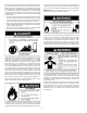
SECURING WATER HEATER TO FLOOR AND WALL
(USE METHOD A OR B)
The water heater must be secured to the fl oor and to the wall of the
enclosure.
METHOD A: use the three mounting brackets and screws packaged
in the carton with the water heater. The two small brackets are used to
attach the water heater to the fl oor and the one large bracket is used
to secure the top of the water heater to the wall.
METHOD B: use metal tape also called “plumbers tape” to secure the
water heater to the enclosure. See the fi gure below as reference for
attaching the tape.
Because of installation variances, these brackets can be located at
any points around the circumference of the jacket. When the bracket
locations are determined, use a 1/8 inch SAE drill bit to set a pattern.
Drill only through the outer jacket of the water heater. Then using the
screws provided, secure the bracket to the water heater, fl oor and
wall. See Figure 12.
ONE LARGE MOUNTING
BRACKET AT TOP
TWO SMALL MOUNTING
BRACKETS AT BOTTOM
TWO STRAPS OF METAL
TAPE AT THE TOP
TWO STRAPS OF METAL
TAPE AT THE BOTTOM
METHOD A METHOD B
FIGURE 12.