Installation Instructions and Use & Care Guide RESIDENTIAL GAS WATER HEATERS POWER DIRECT VENT GAS MODELS WITH HOT SURFACE IGNITION NOT FOR USE IN MANUFACTURED (MOBILE) HOMES WARNING: If the information in these instructions is not followed exactly, a fire or explosion may result causing property damage, personal injury or death. - Do not store or use gasoline or other flammable vapors and liquids in the vicinity of this or any other appliance.
TABLE OF CONTENTS Safe Installation, Use And Service . . . . . . . . . . . . . . . . . 3 General Safety . . . . . . . . . . . . . . . . . . . . . . . . . . . . . . . . 4 Introduction. . . . . . . . . . . . . . . . . . . . . . . . . . . . . . . . . . . 6 Qualified Installer Or Service Agency . . . . . . . . . . . . . 6 Preparing For The Installation . . . . . . . . . . . . . . . . . . . 6 Installation Requirements For The Commonwealth Of Massachusetts . . . . . . . . . . . . . . . . . . . . . . . . . . . . .
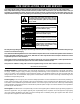
SAFE INSTALLATION, USE AND SERVICE Your safety and the safety of others is extremely important in the installation, use and servicing of this water heater. Many safety-related messages and instructions have been provided in this manual and on your own water heater to warn you and others of a potential injury hazard. Read and obey all safety messages and instructions throughout this manual.
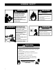
GENERAL SAFETY WARNING Read and understand instruction manual and safety messages before installing, operating or servicing this water heater. Failure to follow instructions and safety messages could result in death or serious injury. Instruction manual must remain with water heater. DANGER WARNING Fire Hazard For continued protection against risk of fire: • Do not install water heater on carpeted floor. • Do not operate water heater if flood damaged.
GENERAL SAFETY CAUTION Improper Installation, use and service may result in property damage. • Do not operate water heater if flood damaged. • Inspect anode rods regularly, replace when significantly depleted. • Install in location with drainage. • Fill tank with water before operation. • Properly sized thermal expansion tanks are required on all closed water systems. Refer to this manual for installation and service.
INTRODUCTION Thank You for purchasing this water heater. Properly installed and maintained, it should give you years of trouble free service. Abbreviations found in this Installation and Operating manual: • CSA - Canadian Standards Association • ANSI - American National Standards Institute • NFPA - National Fire Protection Association • ASME - American Society of Mechanical Engineers • UL - Underwriters Laboratories Inc. • AHRI - Air Conditioning, Heating and Refrigeration Institute.
INSTALLATION REQUIREMENTS FOR THE COMMONWEALTH OF MASSACHUSETTS COMMONWEALTH OF MASSACHUSETTS For all side wall terminated, horizontally vented power vent, direct vent and power direct vent gas fueled water heaters installed in every dwelling, building or structure used in whole or in part for residential purposes, including those owned or operated by the Commonwealth and where the side wall exhaust vent termination is less than seven (7) feet above finished grade in the area of the venting, including but n
INSTALLATION GRAPHIC: GAS-FIRED POTABLE WATER HEATING/SPACE HEATING SYSTEM • If your water heater will be installed in the Commonwealth of Massachusetts, refer to the following graphic during installation and during modifications to the water supply system. TYPICAL MIXING VALVE INSTALLATION COMBINATION SPACE HEATING / POTABLE WATER HEATING SYSTEM EXPANSION TANK TEMPERED WATER TO FIXTURES (MUST MEET TEMPS LISTED IN MASS.
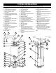
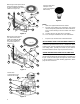
TYPICAL INSTALLATION GET TO KNOW YOUR WATER HEATER - GAS MODELS (LIST REFERENCING FIGURES 1-5) 1 2 3 4 5 6 7 8 9 10 11 12 13 14 15 16 17 Termination Elbow with Vent Screen *Vent Pipe *Vent Pipe Elbow (long radius) Sound Suppressor (Optional) *Union (Di-electric water connection) Cold-Water Inlet Nipple/Diptube **Combo Heating System Supply Outlet (Optional) T&P Valve * Discharge Pipe **Combo Heating System Return Inlet (Optional) Gas Control Valve/Thermostat (Honeywell) Gas Valve Electronic Control Module
Natural gas and Propane main burner with igniter assembly for 40k and 45k Btu/hr models (item 15 in Figure 1) †. 18 35 Vacuum relief valve install per local codes (not supplied with heater). 37 36 38 39 40 41 43 42 Figure 3. Natural gas and Propane (LP) main burner with igniter assembly for 58k, 62k, 72k and 76k Btu/ hr models (item 15 in Figure 1) †. 18 Notes: * Items not supplied with the water heater.
WATER PIPING - MIXING VALVE USAGE Mixing Valves DANGER Water temperature over 125°F can cause severe burns instantly resulting in severe injury or death. Children, the elderly and the disabled and are at highest risk of scald injury. Feel water before bathing or showering. HOT BURN Temperature limiting devices such as mixing must be installed when required by codes and to ensure safe temperatures at fixtures.
Some people are more likely to be permanently injured by hot water than others. These include the elderly, children, the infirm and the physically/mentally disabled. Table 1 (published by U.S. Government Memorandum, 1978) shows the approximate time-to-burn relationship for normal adult skin. If anyone using hot water provided by the water heater being installed fits into one of these groups, special precautions must be taken.
CAUTION: LABEL ALL WIRES PRIOR TO DISCONNECTION WHEN SERVICING CONTROLS. WIRING ERRORS CAN CAUSE IMPROPER AND DANGEROUS OPERATION. VERIFY PROPER OPERATION AFTER SERVICING. POWER VENT WIRING SCHEMATIC. ELECTRICAL REQUIREMENTS & WIRING DIAGRAM WARNING Electric Shock Hazard Disconnect power before servicing. NOTE: REFER TO THE “INSTALLATION CHECKLIST” BEFORE OPERATING THIS HEATER. Replace all parts and panels before operating. 1 N 1 L1 Failure to do so can result in death or electrical shock.
SAFETY LOCKOUTS This water heater has several lockout features designed to prevent the heater from operating in unsafe conditions. The switch will auto reset once the temperature drops sufficiently. HIGH LIMIT CONTROLS (ENERGY CUT OFF) Thermostat/Water Temperature This feature is a part of the gas control valve/thermostat (see Figure 1, item 10) and limits the maximum water temperature. In the event of the water overheating, this safety feature shuts off the fuel supply to the burner.
WARNING Fire or Explosion Hazard • Do not store or use gasoline or other flammable vapors and liquids in the vicinity of this or any other appliance. • Avoid all ignition sources if you smell gas. • Do not expose water heater control to excessive gas pressure. • Use only gas shown on rating plate. • Maintain required clearances to combustibles. • Keep ignition sources away from faucets after extended period of non-use.
WARNING Breathing Hazard - Carbon Monoxide Gas • Flue gases may escape if vent pipe is deformed, broken, or not properly connected. Breathing carbon monoxide can cause brain damage or death. Always read and understand instruction manual. Important Notes and Warnings • This heater is certified to be installed using Schedule • • • • • 16 40 PVC or CPVC or polypropylene plastic vent material. Only use approved material.
INSTALLING THE NEW WATER HEATER WATER PIPING DANGER Water temperature over 125°F can cause severe burns instantly resulting in severe injury or death. Children, the elderly and the disabled and are at highest risk of scald injury. Feel water before bathing or showering. HOT BURN Temperature limiting devices such as mixing must be installed when required by codes and to ensure safe temperatures at fixtures. The water supply pressure should not exceed 80 psi.
COMBO HEATING This section serves as a guide for the installation and use of “Combo” heating systems utilizing a domestic water heater that has been specifically approved for such use. It is written for those knowledgeable in the required trades and professionals involved in the design and installation of Combo Heating Systems. It is the responsibility of the installer/designer to follow all applicable codes to ensure the effectiveness and safety of the installation.
CLOSED WATER SYSTEMS Water supply systems may, because of code requirements or such conditions as high line pressure, among others, have installed devices such as pressure-reducing valves, check valves, and back flow preventers. Devices such as these cause the water system to be a closed system. THERMAL EXPANSION As water is heated, it expands (thermal expansion). In a closed system, the volume of water will increase.
TEMPERATURE-PRESSURE RELIEF VALVE WARNING Explosion Hazard • Temperature-pressure relief valve must comply with ANSI Z21.22-CSA4.4 and ASME code. • Properly sized temperaturepressure relief valve must be installed in opening provided. • Do not plug, block, or cap the discharge line. • Failure to follow this warning can result in excessive tank pressure, serious injury or death.
Note: The purpose of a temperature-pressure relief valve is to prevent excessive temperatures and pressures in the storage tank. The T&P valve is not intended for the constant relief of thermal expansion. A properly sized thermal expansion tank must be installed on all closed systems to control thermal expansion, see “Closed Water Systems” and “Thermal Expansion” sections.
Make sure the gas supplied is the same type listed on the model rating plate. The inlet gas pressure must not exceed 14” w.c. for natural gas and propane gas. The minimum inlet gas pressure shown on the rating plate is that which will permit firing at rated input. All gas piping must comply with local codes and ordinances or with the “National Fuel Gas Code”, ANSI Z223.1/ NFPA 54. Copper or brass tubing and fittings (except tin lined copper tubing) should not be used.
trap must be incorporated in the piping. The sediment trap must be readily accessible. Install in accordance with the “Gas Piping” section. Refer to the current edition of the “National Fuel Gas Code”, ANSI Z223.1/NFPA 54. FILLING THE WATER HEATER CAUTION Property Damage Hazard • Avoid water heater damage. SHUT-OFF VALVE • Fill tank with water before operating.
TERMINATION CLEARANCES (SIDE WALL) ER RN E CO INSIDDETAIL V VENT TERMINAL X AIR SUPPLY INLET G AREA WHERE TERMINAL IS NOT PERMITTED V A D V B B V C V L D FIXEED S CLO B L O V B V BLE OPERA F V D FIXEED LE CLOS B A PER X M I K OR ULAT A B X J B V V GAS REG ER / MET Figure 21. Power Direct Vent Terminal Clearances A above grade, veranda, porch, deck, or balcony B to window or door that may be opened 12 in. I to regulator vent outlet 36 in.
VENTING WARNING CAUTION Improper Installation, use and service may result in property damage. Breathing Hazard - Carbon Monoxide Gas • Install water heater in accordance with the instruction manual and NFPA 54. This unit includes an air intake terminal and an exhaust vent terminal. • To avoid injury, combustion and ventilation air must be taken from outdoors. WARNING • Do not place chemical vapor emitting products near water heater.
Side Wall Vent For Cold Climates Some winter weather conditions present a risk of ice accumulation at the intake termination screen. Such accumulation will restrict intake air flow. If local conditions present this risk, the termination configuration shown in Figure 23 is recommended. This will reduce the possibility of exhaust gas recirculation as well as reduce the chance of ice accumulation.
Tee Termination Installation A Tee fitting as the exhaust termination and a 90° fitting as the air intake termination are permitted on the water heater models listed in Table 2. Note: The sound suppressor must not be installed if the Tee termination is installed. WATER HEATER MAX. EQUIV. VENT MODEL VENT LENGTH DIAM. 40gal, 40K Btu/Hr 50’ 2” 50gal, 45K Btu/Hr 50’ 2” Table 2. When a Tee termination is used, two additional vent screens must be purchased and installed as seen in Figure 26 and Figure 27.
Concentric Vent Termination Installation A concentric vent termination kit (see Table 3) may be used for vertical or horizontal terminations. Figure 30 illustrates the concentric vent kit for a horizontal (side wall) installation. To prevent rain water from entering the exhaust outlet, slope the vent kit at a downward pitch of 1/4” per 5’ away from the inside wall. Ensure the combustion air intake location is above the anticipated snow level.
Multiple Concentric Vent Installation When two concentric vent kits are being installed, the vent hood centers shall be either less than 9.5” apart or more than 43.5” apart. Spacings between 9.5” and 43.5” are not allowed due to the possibility of exhaust cross circulation (see Figure 32). When more than 2 kits are installed only 2 of them shall be less than 9.5” apart. Never install 3 termination kits together less than 9.5” apart (see Figure 33). WALL OR 9.5” MAX 43.
VENT WATER HEATER SIZE HEATER INPUT (Inside MODEL (Btu/hr) Diam.) 40 gal. PRESSURE SWITCH SETTINGS (“ w.c.) 2 PIPE MAX. EQUIV. VENT LENGTH N.O. N.C. 2” -0.32 -2.12 50’ + term. elbow and screen* 3” -0.32 -2.12 125’ + term. elbow and screen* -1.25 -1.42 -1.35 -1.66 -1.25 -1.42 -0.32 -2.12 -1.25 -1.42 62,000 -1.35 -1.66 76,000 -1.25 -1.42 40,000 50 gal 45,000 40 gal. 40,000 50 gal 45,000 50 gal. 58,000 (L.P.) 62,000 3” 2 PIPE MIN. EQUIV. VENT LENGTH 7’ + term.
Vent Screens This water heater includes one (1) pair of more restrictive vent screens and one (1) pair of less restrictive vent screens (see Figure 36 & Figure 37). For safety and optimum efficiency performance, ensure the correct vent screen is installed for the vent length in your installation. A vent screen is required to keep foreign objects, rodents and small birds from entering the venting system.
For heater models 50-58, 50-62, 75-72 & 75-76 with 3” venting (short) VENT LENGTH LESS THAN OR EQUAL TO 20 EQUIVALENT FT. USE THIS SCREEN (SUPPLIED). with 3” venting (long) VENT LENGTH GREATER THAN 20 EQUIVALENT FT. USE THIS SCREEN (SUPPLIED). with 4” venting VENT LENGTH GREATER THAN 50 EQUIVALENT FT. USE THIS SCREEN (SUPPLIED).
WARNING WARNING Fire Hazard Fire or Explosion Hazard • Cans of cement and primer should be closed at all times when not in use to prevent evaporation of chemicals and hardening of cement. • They are also very flammable and should be kept away from heat or flame. • Do not store or use gasoline or other flammable vapors and liquids in the vicinity of this or any other appliance. • Avoid all ignition sources if you smell gas. • Do not expose water heater control to excessive gas pressure.
RECOMMENDED BRUSH* SIZE FOR PRIMER AND CEMENT APPLICATIONS Nominal Pipe (IPS) Brush Size 2 1.5” 3 1.5” - 2.5” *USE ONLY NATURAL BRISTLE Table 5. 3. MAKING THE JOINT A. Cutting Pipe must be squarely cut to allow for the proper interfacing of the pipe end and the fitting socket bottom. This can be accomplished with a miter box saw or wheel type cutter. Wheel type cutters are not generally recommended for larger diameters since they tend to flare the corner of the pipe end.
Figure 40. F. Joint assembly Working quickly, insert the pipe into the fitting socket bottom and give the pipe or fitting a 1/4 turn to evenly distribute the cement. Do not continue to rotate the pipe after it has hit the bottom of the fitting socket. A good joint will have sufficient cement to make a bead all the way around the outside of the fitting hub. The fitting will have a tendency to slide back while the cement is still wet so hold the joint together for about 15 seconds. Figure 41. G.
Connections To The Blower And Air Duct 1. The plastic vent piping connects into the rubber coupling located on the top of the blower assembly. This coupling includes gear clamps to connect the venting to the blower. Important: These connections must be properly seated and tightened to prevent the leakage of flue gases into the area. See Figure 44 thru Figure 48. 2.
3” INLET PIPE 3” VENT PIPE 3” RUBBER COUPLING (SUPPLIED) BLOWER AIR DUCT ADAPTER CONFIGURATION FOR HI-INPUT HEATERS CONNECTED TO 3” VENTING. (OPTIONAL CONFIGURATION FOR LO-INPUT HEATERS CONNECTED TO 3” VENTING.) Figure 47. 4” VENT PIPE 4” INLET PIPE 3”-4” ADAPTER (FIELD SUPPLIED) 3” VENT PIPE, 3” MAX LENGTH 3” RUBBER COUPLING (SUPPLIED.) 3” PIPE (FIELD SUPPLIED) BLOWER AIR DUCT ADAPTER CONFIGURATION FOR HI-INPUT HEATERS CONNECTED TO 4” VENTING. Figure 48.
SOUND SUPPRESSOR (OPTIONAL) The sound suppressor can reduce the noise generated by the water heater heard outside. Depending on the configuration of the water heater, the sound suppressor will be either a 2” or a 3” fitting (see Table 6). The sound suppressor can be fitted to the venting near the blower assembly (see Figure 49 and Figure 50). The sound suppressor has an equivalent vent length of 15’. Venting size Sound suppressor kit # 2” 9009046005 3” 9009059005 Table 6.
INSTALLATION CHECKLIST Note: Use and complete this checklist before lighting the heater. Correct any conditions that do not meet these instructions. Water Heater Location Centrally located with the water piping system. Located as close to gas piping and vent pipe system as possible. Located indoors and in a vertical position. Protected from freezing temperatures. Proper clearances from combustible surfaces maintained and not installed directly on a carpeted floor.
LIGHTING INSTRUCTIONS Read and understand these directions thoroughly before attempting to operate the water heater. Make sure the burner viewport is not missing or damaged. Make sure the tank is completely filled with water before operating the water heater. The gas control valve/thermostat has an “On/Off Switch” and must be turned on before the water heater is operational. Check the label on the front of the water heater near the gas control valve/thermostat for the correct gas.
OPERATING THE TEMPERATURE CONTROL SYSTEM It is recommended that lower water temperatures be used to avoid the risk of scalding. It is further recommended, in all cases, that the water temperature be set for the lowest temperature which satisfies your hot-water needs. This will also provide the most energy efficient operation of the water heater.
GAS CONTROL VALVE/THERMOSTAT 130°F ON/OFF SWITCH TEMPERATURE SETTING DIAL 140°F 150°F 120°F 110°F 155°F 70°F Figure 51. Approximate Temperature Temperature Dial Setting °F Time to induce a 2nd and 3rd Degree burn to adult skin VERY HOT 155 Less than 1 second C 150 About 1.5 seconds B 140 Less than 5 seconds A 130 More than 30 seconds HOT 120 More than 5 minutes LOW 110 Normal shower temp VAC 70 N/A Table 7. Note: The temperatures indicated are approximate.
FOR YOUR INFORMATION START UP CONDITIONS Condensation Whenever the water heater is filled with cold water, some condensate will form while the burner is ON. A water heater may appear to be leaking when in fact the water is condensate. This usually happens when: a. A new water heater is filled with cold water for the first time. b. Burning gas produces water vapor in water heaters, particularly high efficiency models where flue temperatures are lower. c.
PERIODIC MAINTENANCE GENERAL UPKEEP Make it a habit to look around the heater, the vent piping, and the hot and cold water pipes. Do not allow any material to be piled up against the heater. Do not place any object on top of the vent pipes. Every 3 - 6 months or as necessary: • Clean lint from blower, top of heater. Chemical vapor corrosion of the flue and vent system may occur if air for combustion contains certain chemical vapo rs.
BLUE TIPS LIGHT BLUE INNER CONES ARE SATISFACTORY INCORRECT FLAME LAZY YELLOW CORRECT FLAME SOFT BLUE Figure 53. COMBUSTION CHAMBER AND BURNER CLEANING In the event your burner or burner air openings require cleaning, Call your service agency to remove and clean the burner and correct the problem that required the burner to be cleaned.
WARNING Explosion Hazard • Temperature-pressure relief valve must comply with ANSI Z21.22-CSA4.4 and ASME code. • Properly sized temperaturepressure relief valve must be installed in opening provided. • Do not plug, block, or cap the discharge line. • Failure to follow this warning can result in excessive tank pressure, serious injury or death. DRAINING AND FLUSHING Periodic draining and cleaning of sediment from the tank maybe necessary.
ANODE ROD MAINTENANCE CAUTION Property Damage Hazard • Avoid water heater damage. • Inspection and replacement of anode rod required. Anode Rod. The anode rod is a sacrificial metal rod that helps avoid corrosion and premature failure (leaks) in the tank. The anode rod is a consumable item. Inspect the anode rod after the first six months of operation when you drain and flush the tank. Replace the anode rod if it is substantially worn out or depleted (see Figure 55).
LEAKAGE CHECKPOINTS SERVICE If a condition persists or you are uncertain about the operation of the water heater contact a service agency. Use this guide to check a “leaking” water heater. Many suspected “leakers” are not leaking tanks. Often the source of the water can be found and corrected. If you are not thoroughly familiar with gas codes, your water heater and safety practices, contact your gas supplier or qualified installer to check the water heater.
REFERENCE PARTS LISTING Replacement parts may be ordered through your plumber or the local distributor. When ordering replacement parts, always have the following information ready: 1. Model, Serial and Product number 2. Type of gas 3. Item number 4.
Natural gas and Propane (LP) main burner with igniter assembly for 40k and 45k Btu/hr models (item 15 in Figure 1). Flare Nut †† Shown with Junction Box Cover removed for clarity. 28 29 36 † 30 37 44 49 35 38 39 45 48 47 40 46 41 43 42 Figure 62. Notes: * Items not supplied with the water heater. ** The side recirculation loop connections may not be used as the primary water inlet and outlet connections. See “Combo Heating Inlet And Outlet Side Taps”.
TROUBLESHOOTING GUIDELINES These guidelines should be utilized by a qualified service agent. LOCKOUTS Soft Lockout • Occurs when a system safety device trips to break the sequence of operation. The control will try to start the system in a timed basis but will not reinstate operation until the failure is corrected. IGNITION STATE AND TIMING IGNITION STATE Pre-purge TIMING 5 seconds (NG models) 15 seconds (LP models) Hot Surface Igniter (HSI) Warmup 10 seconds Ignition Activation Period (IAP) 3.
SYSTEM STATUS AND ERROR CODES The micro-controller inside the gas control monitors the ignition sequence, temperature settings, and overall operation of the heater. If any of these parameters does not operate properly the controller will shut down the water heater, diagnose the failure and flash an error code. The table below lists the System Status Codes for the Honeywell control. Refer to it and to the “Ignition State And Timing” to diagnose the problem before attempting corrective action.
CORRECTIVE ACTIONS See the table below for corrective actions corresponding to the Corrective Action Number in the “System Status And Error Codes” section above. If following those corrective actions does not resolve the error, refer to “Other Symptoms“ table later in this manual. Corrective Action Number Corrective Action 1 Normal operation, no action necessary. 2 Normal operation, no action necessary. 3 1. Flame rod not properly seated in flame, reposition rod. 2.
Corrective Action Number Corrective Action 8 1. Gas supply is turned off or gas pressure is too low. Ensure supply pressure and manifold gas pressures are within requirements. Manifold pressure is nonadjustable, if gas supply pressure proves correct and manifold pressure is off by more than 0.3” WC replace the control. 2. Low supply voltage - should be 115 - 125 VAC 3. Ensure flame sensor is making good contact with the burner flame and flame is steady. 4.
OTHER SYMPTOMS Problem Insufficient Hot Water Water Is Too Hot Slow Hot Water Recovery Drip From Relief Valve Smelly Water Condensation Possible Cause(S) 1. 2. 3. 4. 5. 6. 7. Thermostat set too low Leaking faucets/Wasted hot water Wrong piping connections Water heater too small Sediment or lime in tank Long runs of exposed piping Hot-water piping in outside wall 1. 2. 3. 4. 5. 6. 7.
®Teflon is a registered trademark of E.I. Du Pont De Nemours and Company LOWE’S is a registered trademark of LF, LLC. A.O. Smith Corporation. All Rights Reserved. Limited Warranty provided by Manufacturer.