On-Demand Water Heater Installation Manual and Owner’s Guide 510U only ANSI Z21.10.3・CSA 4.3 Models • 110U Indoor • 310U Indoor • 510U Indoor • 110U Outdoor • 310U Outdoor • 510U Outdoor Series 200 If the information in these instructions is not followed exactly, a fire or explosion may result causing property damage, WARNING personal injury or death. Gas Tankless Water HeaterTM Suitable for combination potable water heating and space-heating Please refer to local codes for space-heating compliance.
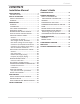
Contents CONTENTS Owner's Guide Installation Manual SPECIFICATIONS..............................................4 INTRODUCTION...........................................5 SAFETY GUIDELINES.....................................6 SAFETY DEFINITION.....................................6 GENERAL.......................................................6 INSTALLATION.................................................7 GENERAL.......................................................7 CLEARANCES.........................
Installation Manual Installation Manual CONGRATULATIONS Congratulations and thank you for choosing our tankless water heater. Before use, we recommend that you read through this installation manual carefully. Keep this manual for future reference. If you need an additional manual, contact the manufacturer or your local distributor. When you call, please tell us the product name and the serial number of your unit written on the rating plate of the water heater.
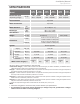
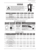
Installation Manual Specifications SPECIFICATIONS 110U Indoor Model Natural Gas Input (Operating Range) BTU/h 110U Outdoor Min.: 15,000 Max.: 140,000 310U Indoor 310U Outdoor Min.: 15,000 Max.: 190,000 Gas Connection 3/4" NPT Water Connections 3/4" NPT Water Pressure* Natural gas Inlet Pressure Weight psi (Mpa) " W.C. (kPa) Consumption Min.: 15,000 Max.: 199,000 Min. 4.0 (1.00) Max. 10.5 (2.61) 37.5 (17.0) 39.7 (18.0) H 20.5 x W 13.8 x D 9.1 (Inch) H 520 x W 351 x D 231 (mm) H 20.
Installation Manual Introduction INTRODUCTION • This manual provides information necessary for the installation, operation, and maintenance of the water heater. • The model description is listed on the rating plate which is attached to the side panel (Indoor models) or the front cover (Outdoor models) of the water heater. • Please read all installation instructions completely before installing this product.
Installation Manual Safety Guidelines SAFETY GUIDELINES SAFETY DEFINITION DANGER WARNING CAUTION NOTICE Indicates an imminently hazardous situation which, if not avoided, will result in death or serious injury. Indicates an imminently hazardous situation which, if not avoided, could result in death or serious injury. Indicates an imminently hazardous situation which, if not avoided, could result in minor or moderate injury. Indicates information considered important but not hazard related.
Installation Manual Installation INSTALLATION GENERAL 1. Follow all local codes, or in the absence of local codes, follow the current edition of the National Fuel Gas Code: ANSI Z223.1/NFPA 54 in the USA or B149.1 Natural Gas and Propane Installation Code in Canada. 2. All gas water heaters require careful and correct installation to ensure safe and efficient operation. This manual must be followed exactly. Read the “Safety Guidelines” section. 3. The manifold gas pressure is preset at the factory.
Installation Manual Installation WARNING CAUTION • Installation and service must be performed by a qualified installer (for example, a licensed plumber or gas fitter). Otherwise, the warranty will be void. • The installer (licensed professional) is responsible for the correct installation of the water heater and for compliance with all national, state / provincial, and local codes. • The manufacturer does not recommend installing the water heater in a pit or location where gas and water can accumulate.
Installation Manual Installation CLEARANCES Top Back Side Maintain all clearances around the water heater. Failure to do so could create a fire hazard, potentially leading to death, serious WARNING injury, and/or property damage. Front Side Bottom Model Top Bottom Front Back Sides 110U Indoor* 12 in. 12 in. 4 in.** 1.0 in. 3 in. 310U Indoor* (305 mm) (305 mm) (102 mm) (25 mm) (76 mm) 510U Indoor* 110U Outdoor*** 36 in. 12 in. 24 in. 1.0 in. 3 in.
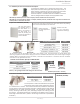
Installation Manual Installation 1. 4” Backflow preventer and Female-female adaptor It prevents the backflow of air through the exhaust vent. This helps prevent harmful exhaust gases from entering the home, as well as helping to prevent the unit from freezing in areas where cold air can be blown or drawn into the exhaust system. Install this adaptor in accordance with the installation instructions that are packaged with the adaptor and any applicable codes.
Installation Manual Installation WARNING FOR INSTALLATIONS FOR YOUR SAFETY, READ BEFORE INSTALLATION: Do not install the heater where water, debris or flammable vapors may get into the flue terminal. This may cause damage to the heater and void the warranty. Do not have the vent terminal pointing toward any opening into a building. Do not locate your water heater in a pit or location where gas and water can accumulate.
Installation Manual Installation HIGH-ALTITUDE INSTALLATIONS Check the elevation where your water heater is installed. Set your DIP switches according to altitude as shown below. • • WARNING • Adjust the appropriate DIP switches according to model and elevation as shown below. DO NOT adjust the other DIP switches. Turn off the power supply to the water heater before changing the DIP switch settings. Failure to observe these warnings could lead to carbon monoxide poisoning or death.
Installation Manual Installation VENTING INSTRUCTIONS For indoor models -General- • Improper venting of this appliance can result in excessive levels of carbon monoxide which can result in severe personal injury or death. • Improper installation can cause nausea or asphyxiation, severe injury or death from carbon monoxide and flue gases poisoning. Improper installation will void WARNING product warranty. • When installing the vent system, all applicable national and local codes must be followed.
• A condensate collector is required for horizontal and/or vertical vent runs exceeding 5 ft of equivalent length (not including sidewall terminatons). • A backflow preventor should be installed in the exhaust when the heater is installed in climates subject to freezing temperatures. General rules for vent terminations: • Avoid locating the water heater vent termination near any air intake devices. These fans can pick up the exhaust flue products from the water heater and return them to the building.
-Combustion Air Supply• This gas water heater requires an adequate source of clean air for combustion and ventilation. Without sufficient air, your water heater may not operate properly and may emit excessive and abnormal amounts of carbon monoxide which may result in carbon monoxide poisoning or death.
Calculate the air volume of the room Air requirements depend on the size of the room. Room Volume (ft3) = Floor Area (ft2) X Ceiling Height (ft) If there are large objects in the room (e.g., refrigerator, furnace, car), subtract their volume from the volume of the room to get a better estimate of the air available. Air Volume = Room Volume - Object Volume NOTE: Adjoining rooms with permanently opened doorways can be counted as part of the calculation.
Calculate minimum size of vent openings and ducts The vent cross-sectional area needed to provide the free area depends on the covering on the vent openings. Typical vents use louvers or grilles to protect the opening. The louver or grill itself blocks some of the free area, so the opening may need to be larger to meet the minimum free area requirements.
Combustion Air Supply Options Gable vent to outdoors Install above insulation 12” maximum Outlet air to attic 1 in2 per 4,000 btu/h Confined Space Two permanent Openings Alternate Air Inlet 1 in2 per 4,000 btu/h Inlet air from the crawl space Confined Space 12” maximum 1 in per 4,000 btu/h 2 Open foundation vent Figure 2 - Direct to outdoors openings Two permanent openings Figure 1 - Direct to outdoors openings Gable vent to outdoors 1 in2 per 2,000 btu/h Install above insulation Outlet air to a
Installation Manual Installation -Vent length and No. of ElbowsThe vent system must be sealed airtight. All seams and joints without gaskets must be sealed with high heat resistant silicone sealant or UL listed aluminum adhesive tape having a minimum temperature rating of 350 °F (177 °C). For best results, a vent system should be as short and straight as possible. • This water heater is a Category III appliance and must be vented accordingly with any 4 in.
-DIP Switch Settings for Vent Length• Improper venting of this appliance can result in excessive levels of carbon monoxide which can result in severe personal injury or death. • Improper installation can cause nausea or asphyxiation, severe injury or death from carbon monoxide and flue gases poisoning. Improper WARNING installation will void product warranty. • Specific DIP switch settings are required depending on the length of your vent run and the type of vent installation.
Installation Manual Installation Two-Pipe, Direct-Vent Installation Examples DIP switch settings for direct vent installation 110U Indoor 310U Indoor ON 1 2 3 4 5 6 7 8 9 10 OFF ON 1 2 3 4 5 6 7 8 9 10 OFF ON 1 2 3 4 5 6 7 8 9 10 OFF 510U Indoor (Upper bank of DIP switches) No. 6 : O N No. 7 : OFF No. 8 : OFF No. 6 : OFF No. 7 : OFF No. 8 : OFF No. 6 : O N No. 7 : O N No. 8 : OFF ON 1 2 3 4 5 6 7 8 OFF ON 1 2 3 4 5 6 7 8 OFF ON 1 2 3 4 5 6 7 8 OFF Vent length No. 3 : O N No. 4 : OFF No.
Installation Manual Installation Horizontal Installation with the 100187154 vent kit For the Direct vent kit of 100187154, set the following DIP switch settings. 110U Indoor 310U Indoor ON 1 2 3 4 5 6 7 8 9 10 OFF Single Pipe with Room-Air Intake 510U Indoor (Upper bank of DIP switches) No. 6 : O N No. 7 : O N No. 8 : OFF ON 1 2 3 4 5 6 7 8 OFF Vent length No. 3 : ON No. 4 : ON No. 5 : OFF 0 to 55 ft (0 to 16.
Installation Manual Installation -Clearances for sidewall terminationsImproper installation can result in carbon monoxide poisoning or death. Follow all local and national codes in regards to proper termination clearances. In the absence of such codes, the clearances below must be met. Local codes supersede these clearances. WARNING Failure to observe this warning may result in severe personal injury or death.
Installation Manual Installation -Clearances for rooftop terminationsImproper installation can result in carbon monoxide poisoning or death. Follow all local and national codes in regards to proper termination clearances. In the absence of such codes, the clearances below must be met. Local codes supersede these clearances. WARNING Failure to observe this warning may result in severe personal injury or death. Angled roof termination Flat roof termination 2 ft (610 mm) min. 3 ft (914 mm) min.
Installation Manual Installation -Vent termination clearancesInside corner detail V = Vent terminal X = Air supply inlet G = Area where the terminal is not permitted V D H A V L E V B B C Fixed closed Operable V F B Fixed Operable closed V B V X V B V M I J A X V K Regulator/Gas meter vent outlet B Canada Installations1 Direct vent and other than direct vent Direct vent US Installations2 Other than directdvent A Clearance above grade, veranda, porch, deck, or balcony 1 ft (30
Installation Manual Installation GAS SUPPLY AND GAS PIPE SIZING -General• Do not use this water heater with any gas other than the one listed on the rating plate unless the water heater has been properly converted. • Ensure that any and all gas regulators used are operating properly and providing gas pressures within the specified range shown below. Excess gas WARNING inlet pressure may cause serious accidents.
Installation Manual Installation -Natural Gas Supply Piping- Maximum delivery Capacity in Cubic Feet of Gas per Hour (based on IPS Pipe carrying Natural Gas with 0.60 Specific Gravity with a Pressure Drop of 0.5" W.C.). Based on Energy Content of 1,000 BTU/Cubic ft: The water heater requires 140 Cubic ft/hr for the 110U, 190 Cubic ft /hr for 310U, and 199 Cubic ft/hr for the 510U model. The following tables are from NFPA 54. Unit: Cubic feet per hour Pipe Size Diameter: 10' (3.0) in.
Installation Manual Installation WATER CONNECTIONS WARNING Do not use this appliance if any part has been under water. Immediately contact a qualified installer or service agency to replace a flooded water heater. Do not attempt to repair the unit! It must be replaced! Do not reverse the hot outlet and cold inlet connections to the water heater. This will prevent the water heater from activating properly.
Installation Manual Installation ELECTRICAL CONNECTIONS • • WARNING • • Ensure that circuit power is turned OFF before you complete the following steps. Follow the electrical code requirements of the local authority having jurisdiction. In the absence of such requirements, follow the current edition of the National Electrical Code ANSI/NFPA 70 in the U.S. or the current edition of CSA C22.
Installation Manual Installation TEMPERATURE REMOTE CONTROLLER • • -Included accessories-Outdoor models only The remote control is an optional accessory that can be installed in a hall, closet, etc., to allow for temperature adjustment without having to go to the heater. When installed, the remote will take priority over the built-in controller of indoor models. Verify that the items listed below are included with the remote controller.
Installation Manual Installation 4. Tighten the two "Fork terminals" beneath the two "Remote controller terminal" screws on the back of the main body. (Fig. D-1) 5. Cut out the inlet for the remote controller cable from the bottom of the main body. (Fig. D-2) 6. Place the "Main body" back on the "Back plate", with the "Remote controller cable" running out of the bottom inlet. Fig. D-1 Remote controller terminals Fig.
Installation Manual Installation EASY-LINK SYSTEM 510U model only The 510U model water heaters can be connected with other allowable heaters (see the table below) with communication cables to work as a multiple-unit manifold system. • The built-in Easy-Link System allows up to 4 units to manifold together. • A communication cable (gray color) comes with each 510U model. You can manifold from 2 to 4 units without the need for a multi-unit controller.
Installation Manual Installation 6. Between the “CHILD-1” and the “CHILD-2” units: Connect the “2” connector of the “CHILD-1” unit to the “1” connector of the “CHILD-2” unit. 7. Between the “CHILD-2” and the “CHILD-3” units: Connect the “2” connector of the “CHILD-2” unit to the “1” connector of the “CHILD-3” unit. 8. Verify that all cables are connected like the diagram (B). 9. Turn on power to the “PARENT” unit. Next, turn on “CHILD-1”.
Installation Manual Installation MULTI-UNIT SYSTEM Multiple 510U models can be combined for a Multi-Unit System, along with the multi-unit controller (Part 100112691 (TM-MC02)). Each multi-unit controller can control from 2 to 20 units for commercial or residential applications. For a 20-unit system, the computer can modulate from 15,000 BTU/h to 3.98 million BTU/h. An individual cut-off switch is recommend- 100112691 510U ed for each unit in a Multi-Unit System for (TM-MC02) the purpose of maintenance.
Applications APPLICATIONS SPACE-HEATING APPLICATIONS • This water heater is suitable for combination water (potable) heating and space heating and not suitable for space heating applications only. • In order to purge air in water pipes within a closed-loop system, an air vent and air separator should be installed in the system. Required circulation flow rates are labeled next to each application diagram. These flow rate requirements must be WARNING followed.
Installation Manual Installation DUAL-PURPOSE HOT WATER HEATING (Domestic and Space Heating): Diagrammatic layout of radiant heating and domestic water heater. Tempered water to plumbing fixtures.
Installation Manual Initial operation INITIAL OPERATION FOR YOUR SAFETY, READ BEFORE OPERATING • Check the GAS and WATER CONNECTIONS for leaks before firing the unit for the first time. • Open the main gas supply valve to the unit using only your hand to avoid any spark. Never use tools. If the knob will not turn by hand, do not try to force it; call a qualified service technician. Forced repair may result in a fire or explosion due to gas leaks.
Owner's Guide Owner's Guide CONGRATULATIONS Congratulations and thank you for choosing our tankless water heater. Before use, we recommend that you read through this owner's guide carefully. Keep this manual for future reference. If you need an additional manual, contact the manufacturer or your local distributor. When you call, please tell us the product name and the serial number of your unit written on the rating plate of the water heater.
Owner's Guide Operating Safety OPERATING SAFETY FOR YOUR SAFETY READ BEFORE OPERATING WARNING: If you do not follow these instructions exactly, a fire or explosion may result causing property damage, personal injury or loss of life. A. This appliance does not have a pilot. It is equipped with an ignition device which automatically lights the burner. Do not try to light the burner by hand. B. BEFORE OPERATING smell all around the appliance area for gas.
Owner's Guide Operating Safety DANGER Vapors from flammable liquids will explode and catch fire causing death or severe burns. Do not use or store flammable products such as gasoline, solvents or adhesives in the same room or area near the water heater. Flammable Vapors FLAMMABLES Do not install water heater where flammable products will be stored or used unless the main burner is at least 18” above the floor. This will reduce, but not eliminate the risk of vapors being ignited by the main burner.
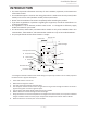
Owner's Guide Normal Operation NORMAL OPERATION BUILT-IN CONTROLLER AND REMOTE CONTROLLER The illustration below shows an example of the controllers. The exact display may differ from examples. Remote controller Built-in controller Display for Temperature When the STAND BY LED is ON, the hot water temperature will be displayed. "INFO" Button Each time the button is pressed, the operation mode is selected in the sequence of the following.
Owner's Guide Normal Operation TEMPERATURE SETTINGS -Set temperatureScreen on the controller Operation Built-in controller 1. Turn on the 120 VAC power supply to the unit (the water heater or the multi-unit controller). 2. Press the "ON/OFF" button on the controller in order to turn the controller on. 3. When ON, the STAND BY LED is lit. 4. It shows the set temperature on its display as shown in the picture on the right. (EX.: 120 °F) Remote controller (EX.
Owner's Guide Normal Operation -Additional featuresInformation mode You can get some information about the water heater's condition by pressing the "INFO" button. For more information, follow the procedures below: Screen on the controller INFO Button Operation 1st. press Inlet water temperature will be displayed on the remote controller by pressing the "INFO" button. Inlet water temperature 2nd. press Outlet water temperature will be displayed on the remote controller by pressing the "INFO" button.
Owner's Guide Normal Operation TEMPERATURE SETTINGS ON THE PCB WITHOUT CONTROLLER • • WARNING • Adjust the appropriate DIP switches according to model and temperature as shown below. DO NOT adjust the other DIP switches. Turn off the power supply to the water heater before changing the DIP switch settings. Failure to observe these warnings could lead to carbon monoxide poisoning, severe personal injury, or death.
Owner's Guide Normal Operation FREEZE PROTECTION SYSTEM • This unit comes equipped with heating blocks to protect it from damage associated with freezing. • For this freeze protection system to operate, there has to be electrical power to the unit. Damage to the heat exchanger caused by freezing temperatures due to power loss is not covered under the warranty. In cases where power losses can occur, consider the use of a backup power supply.
Owner's Guide Normal Operation -Measuring inlet gas pressure1. Turn off all electric power to the water heater if service is to be performed. 2. Turn the manual gas valve located on the outside of the unit to the OFF position. 3. Failure to follow these steps could lead to fire or explosion, resulting in personal injury or death. WARNING The water heater cannot perform properly without sufficient inlet gas pressure. Below are instructions on how to check the inlet gas pressure.
Owner's Guide Troubleshooting TROUBLESHOOTING GENERAL TEMPERATURE and AMOUNT OF HOT WATER PROBLEM SOLUTIONS It takes a long time to • The time it takes to deliver hot water from the water heater to your get hot water at the fixtures depends on the length of piping between the two. The longer fixtures. the distance or the bigger the pipes, the longer it will take to get hot water.
Owner's Guide Troubleshooting PROBLEM EASY-LINK SYSTEM 510U model only • • • • • • • The fan motor is still spinning after operation has stopped. Unit sounds abnormal while in operation Built-in and remote controller do not display anything when the power button is turned on. Buit-in controller and remote controller WATER HEATER Unit does not ignite when water goes through the unit. SOLUTIONS • • Is the flow rate over 0.5 GPM (1.9 L/min)? (p. 41) Check the filter on the cold water inlet. (p.
Owner's Guide Troubleshooting ERROR CODES -General- • The units have self-diagnostic functions for safety and convenience when troubleshooting. • If there is a problem with the installation or the unit, the error code will be displayed on the built-in controller or remote controller. • Consult the table on the following pages for the description of each error code.
-For the 510U model in an Easy-Link SystemError codes will be displayed differently with units installed within an Easy-Link System, not only to show what the error code is, but to also indicate which unit within the system has the error code. Below is a sample of how the error code of "321" is displayed in an Easy-Link System.
Owner's Guide Troubleshooting -Fault Analysis of Error Codes- If the error code is displayed on the computer board of the water heater or the controller, please check the following. After checking, consult with the manufacturer.
Owner's Guide Troubleshooting Remote Green LED Malfunction description Diagnosis 510 Six Flashes Abnormal main gas solenoid valve • Check for connection/breakage of wires (Part #708) and/ or burn marks on the computer board (Part #701). 551 Six Flashes Abnormal gas solenoid valve • Check for connection/breakage of wires (Part #714) and/ or burn marks on the computer board (Part #701).
Owner's Guide Components Diagram COMPONENTS DIAGRAM Case assembly 052 003 052 004 003 052 007 001 007 001 008 050 710 002 704 715 006 008 050 050 704 002 050 052 Built-in temperature controller 722 721 065 53 Page 005 052
Owner's Guide Components Diagram Computer board assembly 110U and 310U 711 510U 711 701 708 701 705 705 709 708 408 407 103 714 709 403 103 402 402 402 713 402 714 721 721 707 713 707 064 712 712 Surge box assembly 120 053 062 703 068 704 705 706 716 705 54 Page
Owner's Guide Components Diagram 401 Burner assembly Burner assembly 114 101 119 709 107 106 118 053 105 103 115 109 054 060 061 053 110 102 057 111 108 711 104 122 053 153 112 Manifold assembly 062 154 053 113 121 401 062 708 701 711 053 062 062 150 053 055 117 067 707 103 714 063 116 151 702 053 152 510U 056 055 057 052 052 054 Exhaust section (Outdoor model) LP Conversion Kit 130 104 122 131 55 Page
Owner's Guide Components Diagram Water Way assembly 401 414 403 458 456 463 460 A 462 B Bypass section 510U 413 450 450 451 452 452 412 A To Water inlet section 414 450 401 460 D 451 458 462 C 059 456 414 110U 310U 453 B To Water outlet section 066 416 D 451 459 454 411 To Water inlet section 414 462 414 451 052 417 458 458 510U 461 C To Water outlet section 402 460 510U 461 456 454 408 C D 058 404 458 052 052 415 457 415 409 455 410 405 454 40
Owner's Guide Parts List PARTS LIST Part # Item # 001 002 003 004 005 006 007 008 050 051 052 053 054 055 056 057 058 059 060 061 062 063 064 065 066 067 068 101 102 103 104 105 106 107 108 109 110 111 112 113 114 115 116 117 AT-KJr3U-IN/OS, Description 110U, 310U and AT-K5U-IN/OS and 510U models AT-D3U-IN/OS N/A N/A N/A N/A EK596 EK597 EK598 EK599 Bracket Intake air port assembly Junction box Power supply cord assembly Back guard panel Overheat-cut-off fuse for combustion chamber Truss screw M4×12 (W
Owner's Guide Parts List Part # Item # AT-KJr3U-IN/OS, Description 118 119 120 121 122 130 131 150 151 152 153 154 401 Burner gasket Burner holder gasket Surge box plate PCB fixing plate Thermostat LP Conversion kit Manifold gasket O-ring P18 NBR (Manifold) O-ring P20 NBR (Black) Silicon ring for Outdoor models Rain protection plate in Exhaust chamber for Outdoor models Exhaust port for Outdoor models Heat exchanger assembly for 110U and 310U Indoor for 110U and 310U Outdoor for 510U Indoor for 510U Out
Owner's Guide Parts List Part # Item # 701 702 703 704 705 706 707 708 709 710 711 712 713 714 715 716 721 722 N/A AT-KJr3U-IN/OS, Description 110U, 310U and AT-K5U-IN/OS and 510U models AT-D3U-IN/OS Computer board for 110U model for 310U model for 510U model Remote fixing plate for 510U Surge box 120 VAC wire for Indoor models for Outdoor models Switch wire 120 VAC Power ON-OFF switch Remote controller wire for 110U and 310U for 510U Gas valve wire Flame rod wire Cable strap Igniter assembly Computer b
Owner's Guide Output Temperature Chart OUTPUT TEMPERATURE CHART Chart is based on properly sized gas line Output Hot Water GPM 110U Output Temperature vs. GPM (Max. 6.6 GPM) with Various Inlet Water Temperature Incoming Temp. (°F) Set Temp. (°F) 310U Incoming Temp. (°F) Output Hot Water GPM Output Temperature vs. GPM (Max. 8.0 GPM) with Various Inlet Water Temperature Set Temp. (°F) Output Hot Water GPM 510U Output Temperature vs. GPM (Max. 10.