Service Handbook Residential FVIR Gas Water Heaters MODELS: GCV, GCVH, GVR, GCVL, GVRL, GCVT - SERIES 300/301 XCV, XVR, XCVL, XGV, XVRL, XCVT - SERIES 300/301 LOW LEAD CONTENT THIS SERVICE HANDBOOK IS FOR USE BY QUALIFIED SERVICE PROFESSIONALS ONLY.
TABLE OF CONTENTS General Safety .................................................................................................................................................... 4 BASICS Completed Installation (typical) ......................................................................................................................... 6 System Basics ....................................................................................................................................................
Tank Leak............................................................................................................................................................................... 15 Leaking Plumbing Connections ............................................................................................................................... 15 Drips from the T&P Relief Valve Discharge Pipe .....................................................................................................
BASICS GENERAL SAFETY Your safety and the safety of others is extremely important in the servicing of this water heater. Many safety-related messages and instructions have been provided in this handbook and on your water heater to warn you and others of a potential hazard. Read and obey all safety messages and instructions throughout this handbook as well as those found in the Installation Instructions/ Use & Care Guide.
BASICS Fire or Explosion Harzard Do not store or use gasoline or other flammable vapors and liquids in the vicinity of this or any other appliance. Avoid all ignition sources if you smell Natural or LP gas. Do not expose water heater control to excessive gas pressure. Use only gas shown on rating plate. Maintain required clearances to combustibles. Keep ignition sources away from faucets after extended period of non-use. Read instruction manual before installing, using or servicing water heater.
BASICS COMPLETED INSTALLATION ΈTYPICALΉ See Labels and Installation Instructions and Use & Care Guide for clearances. Exhaust Vent to Ouside of Building Union Union Untempered Hot Water Cold Water Inlet Water Shut-Off Valve *Massachusett: Install a vacuum relief in cold water line per section 19 MGL 142. Expansion Tank Pressurized to Equal Supply Water Pressure* (Relieve water pressure on the expansion tank before adjusting air pressure.
Honeywell® Gas Control Valve/Thermostat error codes, see “Lighting the Pilot / Diagnostic Flash Codes” on page 9. Water heaters covered by this handbook are equipped with Honeywell gas control valve/thermostats. WŝůŽƚ ŇĂŵĞ ŚĞĂƚƐ ƚŚĞƌŵŽƉŝůĞ͕ ĞŶĂďůŝŶŐ ŐĂƐ ĐŽŶƚƌŽů ǀĂůǀĞͬ ƚŚĞƌŵŽƐƚĂƚ ŽƉĞƌĂƟŽŶ͘ Pilot • The Honeywell valve uses a thermopile instead of a thermocouple as did previous designs. T r he m op ile • Heat on the thermopile generates 750 to 900 millivolts (open circuit).
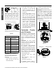
BASICS Scalding Risk A water heater can make water hot enough to cause severe burns instantly, resulting in severe injury or death. Higher temperatures increase the risk of scalding, but even at 120°F, hot water can scald. See Table 2. Thermostatic mixing valves at each point of use reduce the risk of scalding. HONEYWELL® GAS CONTROL VALVE/THERMOSTAT GAS CONTROL/TEMPERATURE KNOB §150°F §140°F §155°F §130°F 120°F MARK VAC STATUS LIGHT §55°F IGNITER TEMPERATURES SHOWN ARE APPROXIMATES AND MAY VARY.
LIGHTING THE PILOT / DIAGNOSTIC FLASH CODES 1. Read and follow the lighting instructions on the water heater’s label. 2. Turn the control knob to “Pilot.” Press the knob in fully and hold it in. (The knob will travel in about 1/4inch if it is set to Pilot correctly.) 3. While holding the control knob in, click the igniter button continuously for up to 90 seconds or until the Status Light begins to blink. If the status light does not begin to blink after 90 seconds, STOP. Release the control knob.
PILOT/FLASH CODES 7. Wait 10 minutes and try to light the Pilot according to the instructions on the water heater’s label. 8. While clicking the igniter button continuously, the control knob must be set to Pilot and held in until the Status Light blinks. Once the status light blinks, release the control knob and set the knob to the desired temperature setting. (“Hot” is approximately 120°F.
SYSTEM CHECKS Explosion Risk WARNING! Before performing any test, check the area around the water heater for any source of a flammable vapor (i.e gasoline, paint thinners, etc.). If any sources are found, do not proceed until they are removed. DraŌ Test WARNING! Burn Hazard. Do not touch the vent. Doing so can cause burns. After successfully lighting the water heater, allow the main burner to operate for five minutes.
Table 3. Gas Pressures 2. Insert multimeter leads into the connectors. The multimeter must be set to read millivolts DC (on a scale that can read 750 millivolts). Reference Figure 12. IF . . . . . . THEN ...the supply gas pressure is lower than required... • increase the supply gas pressure regulator setting Thermopile Check (Closed Circuit) Follow the lighting instructions to light the pilot. Once the pilot is lit, you can check the output of the thermopile with one of the following tests.
COMMON ISSUES WARNING! Do not attempt to light the water heater if flammable vapors or liquids are present. Do not store or use gasoline or other flammable vapors and liquids in the vicinity of this or any other gas appliance. Storage of or use of gasoline or other flammable vapors or liquids in the vicinity of this or any other appliance can result in serious injury or death. No Hot Water If water is not being heated, check the following: 1. Look at the gas control valve/ thermostat.
and early spring months. Even when the water heater is working properly, it may take longer to fully heat the water. As a result, hot water may not be available as quickly as it is during warmer months. to adjust the thermostat. If there still isn’t enough hot water, set the thermostat to a higher setting and install a thermostatic mixing valve at each point of use. An Increase in Hot Water Usage Faulty Shower Control Valve/Faucet Valve Check the hot water at all faucets in the home.
condensation regularly. In that case, a larger water heater is recommended. CondensaƟon NOTE: Condensation may cause a “2 Flashes” error code, indicating low thermopile voltage. This condition may clear up as the tank begins to warm. See “2 Flashes” on page 10 If you see small puddles of water in the drain pan or hear sizzling sounds as water drips on the burner, the water heater may be producing condensation. Condensation may drip onto the burner or other hot surfaces to produce a sizzling sound.
Temperature Too High Scalding Risk A water heater can make water hot enough to cause severe burns instantly, resulting in severe injury or death. Higher temperatures increase the risk of scalding, but even at 120°F, hot water can scald. See Table 2 on page 8 before proceeding. Thermostatic mixing valves at each point of use reduce the risk of scalding.
SERVICE PROCEDURES 1. Turn the gas control/temperature knob to the “OFF” position (Figure 6 on page 9). 2. Before performing any maintenance, it is important to turn off the gas supply to the water heater at the manual gas shutoff valve (Figure 1, p. 6). This valve is typically located beside the water heater. Note the position of the shut-off valve in the open/on position, then proceed to turn it off. 3.
B. Installing the New Pilot/ Thermopile Assembly 1. Read this step carefully before proceeding. Using the old pilot/ pilot tube assembly as a guide, bend the new pilot tube to match the old one. Make only the bends closest to the pilot before going to the next step. 2. Route the new pilot tube and wires through the opening in the manifold door. See Figure 18 on page 17. 4. Reinstall the manifold component block in the manifold door. Ensure that the pilot tube and wires are positioned as shown in Figure 21.
4. Inspect the door gasket and make sure there is no fiberglass insulation between the gasket and the combustion chamber. (Figure 22.) Replacing the Manifold/ Burner Assembly 5. Tighten the two screws that secure the manifold/burner assembly to the combustion chamber. (Use a 1/4” nut driver.) There should be no space between the gasket part of the manifold door and combustion chamber Explosion Risk WARNING! • Tighten both manifold door screws securely.
part on the pilot or pilot assembly. If no spark is visible, check the wire connections and make sure that the electrode is not broken. See also “Connections Check” (p. 11). B. Replace the igniter if defective (i.e., gas control valve/ thermostat and/or pilot/ thermopile assembly). Dirt and rust on the pilot or electrode tip can prevent the igniter spark. Wipe clean with a damp cloth and dry completely.
SUPPLEMENTS WARNING! Gas water heaters require an adequate source of clean air for combustion and ventilation. Without sufficient air, a water heater will have frequent pilot outages and may emit excessive and abnormal amounts of carbon monoxide. Before beginning: Calculate total BTU/HR rating of all appliances To calculate the combusƟon air and venƟlaƟon required, add up the total BTU/HR raƟngs of all gas burning appliances (e.g., water heaters, furnaces, clothes dryers) in the same area.
room to get a better estimate of the air available. Room Volume – Object Volume = Air Volume A2: Calculate required air volume A water heater installed in an unconfined attic or garage requires that the space be at least 50 cubic feet per 1,000 BTU/ HR of the total input for all gas burning appliances in the same area. [Total BTU/HR/1000] x 50 = Cubic feet of air required.
CombusƟon Air Supply OpƟons Minimum Free Area of Permanent Openings for VenƟlaƟon and CombusƟon Air Supply – All Air from Outdoors Only. WARNING! • In all cases, a water heater must be installed according to its installation manual. • Consult the local codes of your area for specific ventilation and combustion air requirements. In the absence of local codes, follow the National Fuel Gas Code (ANSI Z223.1current edition).
Elevated Air Temperature: Volume Requirement Formula: In some areas, attics can reach in excess of 160°F. Such high temperatures can cause atmospherically-vented water heaters to stall and shut down. (Inputs in Btu/hr ÷ 1,000) 50 = minimum volume in cubic feet for all gas appliances in the attic Why? The flame arrestors, filters, and sealed combustion chambers that make modern water heaters flammable vapor ignition resistant also make them more sensitive to high ambient temperatures.
• The draft hood must be installed properly and must not be modified in any way. • The water heater must not be common vented with any power vented appliance. • Horizontal runs of vent should be sloped upward from the water heater by at least ¼-inch per foot. Ensure that there are no dips or sags in the vent run. • The vent run should include as few bends as possible. Each bend increases resistance to the flow of flue gasses.
air openings). See “Pilot Outage: Insufficient Makeup Air” and “Pilot Outage: Decompression” for more information (pp. 24 & 25, respectively). In the short term, however, open a hot water faucet and allow the water to flow until it reaches a safe temperature. FIELD INSTALLATION OF DRAFT HOODS 2 • The purpose of this section is to show how to properly connect draft hoods to single- and double-wall (Type B) vent pipe. These instructions cover 3-inch, 4-inch, and combination draft hood sizes.
• Single Wall - Galvanized Steel • Double Wall (Type B) - Galvanized Steel InstallaƟon Procedure 1. Determine the size of the draft hood. To determine the size of a draft hood, measure across the portion that will fit into the vent or vent connector. (Vent connection will be covered later.) Example: DĞĂƐƵƌŝŶŐ Ă ŽŵďŝŶĂƟŽŶ ƌĂŌ ,ŽŽĚ the legs into the slots, then secure them with screws as described in your installation manual. 3. Connect the draft hood to the venting system as described below. Figure 30.
• When transition to a larger vent size is required, the vent transition connection must be made at the draft hood outlet. Do not connect a 4-inch draft hood to 3-inch vent pipe. A draft hood must only be connected to an equal or largersized vent pipe (as allowed by code). Only use the draft hood that is supplied with the water heater. ^ĞĂů ũŽŝŶƚ Ăƚ ďŽƩŽŵ of vent pipe Increaser 4-inch Vent Pipe Type B DraŌ Hood Connectors Double wall (Type B) vent pipe will not fit draft hoods properly.
NOTES NOTES Residential Standard Gas Water Heater Service Handbook • 29
NOTES NOTES 30 • Residential Standard Gas Water Heater Service Handbook
NOTES NOTES Residential Standard Gas Water Heater Service Handbook • 31
COPYRIGHT © 2014 A.O. SMITH CORPORATION. ALL RIGHTS RESERVED. ALL TECHNICAL AND WARRANTY QUESTIONS SHOULD BE DIRECTED TO THE LOCAL DEALER FROM WHOM THE WATER HEATER WAS PURCHASED. IF YOU ARE UNSUCCESSFUL, CONTACT A.O. SMITH WATER HEATERS RESIDENTIAL TECHNICAL ASSISTANCE AT 1-800-527-1953 OR WWW.HOTWATER.COM.