
Operating Instructions and Installation Instructions


PHE 50 / 75 / 100 / 150 / 175 / 225 / 250 / 275
4
Platenwarmtewisselaar / Plate Heat Exchanger / Échangeur de Chaleur à Plaques
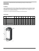
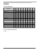
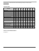
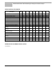
TECHNICAL DATA
Description Unit
PHE
50
PHE
75
PHE
100
PHE
150
PHE
175
PHE
225
PHE
250
PHE
275
Power kW 50 75 100 150 175 225 250 275
Number of plates 20 24 30 40 50 60 70 80
Temperature primary °C 80/60 80/60 80/60 80/60 80/60 80/60 80/60 80/60
Temperature secondary °C 10/60 10/60 10/60 10/60 10/60 10/60 10/60 10/60
Flow primary m³/h 2.15 3.23 4.31 6.46 7.53 9.69 10.77 11.85
Flow secondary m³/h 0.86 1.29 1.72 2.58 3.01 3.87 4.31 4.74
Pressure loss primary kPa 22.7 33.7 37.3 46.4 41.3 48.6 46.2 25.2
Pressure loss secondary kPa 3.3 5.2 5.9 7.6 6.9 8.2 7.8 7.6
Maximum allowed pressure loss kPa 50 50 50 50 50 50 50 50
Maximum operating pressure bar 25 25 25 25 25 25 25 25
Minimum operating temperature °C 0 0 0 0 0 0 0 0
Maximum operating temperature °C 120 120 120 120 120 120 120 120
Material of the plates
AISI
316 L
AISI
316 L
AISI
316 L
AISI
316 L
AISI
316 L
AISI
316 L
AISI
316 L
AISI
316 L
Soldering material copper copper copper copper copper copper copper copper
Empty weight kg 5 5.7 6.7 8.4 10.1 11.8 13.5 15.2
Maximum chlorine concentration
(at 80°C)
mg/kg 50 50 50 50 50 50 50 50
Height of insulating package mm 395 395 395 395 395 395 395 395
Width of insulating package mm 175 175 175 175 175 175 175 175
Depth of insulating package mm 125 125 170 170 215 215 265 265
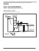
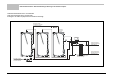
INSTALLATION DIAGRAM EXAMPLES
See appendix 1