
Installation Guide


GENERAL INFO
Electric Tankless Water Heater • 5
GENERAL INFORMATION
Introduction
• This manual provides information
necessary for the installation,
operation, and maintenance of
the water heater.
• The model description is listed on
the rating plate which is attached
to the side panel of the water
heater.
• Please read all installation
instructions completely before
installing this product.
• If you have any problems
or questions regarding this
equipment, consult the
manufacturer or its local
representative.
This appliance is an on-demand,
electric tankless water heater. It is
designed to efficiently supply endless
hot water for your needs.
A built-in alarm is included. If water
leaks inside your electric water
heater, an alarm will sound to provide
warning. Simply turn off power to the
water heater at the circuit breakers,
turn off the water supply, then correct
the leak.
Your water heater also includes
on-board self diagnostics. If the
system produces an error code, see
“Troubleshooting” on one of the
following pages:
• Point-of-use models: page 17.
• Two- or four-chamber models:
page 19.
Component
Descriptions
Temperature and Pressure
Relief Valve
In most cases, you are not required
to install a temperature and pressure
relief valve (T&P valve). However,
some local codes do require the
installation of a T&P Valve. If a T&P
valve must be installed, install it on
the hot outlet pipe according to the
valve manufacturer’s instructions and
local code.
If you install a T&P valve, turn on the
water supply to ensure that no water
drips from it. Next, operate the valve
manually two or three times to purge
the trapped air from the top of the
heater’s chamber, then close the
valve. Verify that water has stopped
flowing completely before connecting
the discharge pipe to the valve.
NOTICE: If a temperature and
pressure relief valve is installed, it
must be piped by minimum 1 inch
pipe to a suitable drain capable of
discharging 10 GPM. A splash cover
must be included to protect the
area of attachment to the wall. The
manufacturer will not be responsible
for any water damage that may occur.
WARNING! Do not cap or plug the
T&P relief valve or discharge pipe.
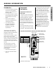
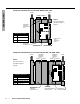
Component Identification: Point-of-Use Models (RPV, CPV)
POWER
SUPPLY
TERMINAL
BLOCK
L1
L2/N
GND
T-Aux
T-In
T-Out
T-Aux
Auxiliary thermistor
T-In
Inlet thermistor
T-Out
Outlet thermistor
Thermistor* Connections
OUTLET INLET
Outlet Thermistor *
(Connects to T-Out)
Auxiliary Thermistor *
(Connects to T-Aux)
Inlet Thermistor *
(Connects to T-In)
* Often referred to
as a temperature
sensor.
Heating Element
(Behind inlet/outlet)
Continued on the next page...