Installa on Instruc ons and Use & Care Guide Electric Tankless Water Heater PLEASE DO NOT RETURN THIS UNIT TO THE STORE. Read this manual and the labels on the water heater before you install, operate, or service it.
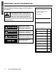
SAFETY IMPORTANT SAFETY INFORMATION Read and follow all safety messages and instruc ons in this manual. This is the safety alert symbol. It is used to alert you to poten al physical injury hazards. Obey all safety messages that follow this symbol to avoid possible property damage, serious injury or death. Do not remove any permanent instruc ons, labels, or the data plate from either the outside of the water heater or on the inside of the access panels. Keep this manual near the water heater.
o reduce the risk of property damage, serious injury or death, read and follow the precau ons below, all labels on the water heater, and the safety messages and instruc ons throughout this manual. • Be sure the cover is reinstalled and secured after servicing to reduce the risk of fire and electric shock.
SAFETY precau ons are par cularly important. According to a na onal standard, American Society of Sanitary Engineering (ASSE 1070), and most local plumbing codes, the water heater’s temperature set point should not be used as the sole means to regulate water temperature and avoid scalds. Properly adjusted Thermosta c Mixing Valves installed at each point of use allow you to set the water heater’s set point to a higher se ng without increasing the risk of scalds.
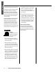
GENERAL INFORMATION Introduction This manual provides information necessary for the installation, operation, and maintenance of the water heater. • The model description is listed on the rating plate which is attached to the side panel of the water heater. • Please read all installation instructions completely before installing this product. • If you have any problems or questions regarding this equipment, consult the manufacturer or its local representative.
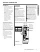
Component Identification: Two-Chamber Models (R2V, C2V) GENERAL INFO OUTLET INLET HEATING ELEMENTS NOTICE: The user interface is described in Figure 7, page 16. Intermediate Thermistor * (connects to TH-1) TH-1 TH-2 TH-IN Thermistor* Connections TH-IN Inlet thermistor TH-1 Intermediate thermistor TH-2 Outlet thermistor L1 L2 * Often referred to as a temperature sensor.
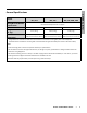
General Specifications Wiring & Circuit Breaker Requirements Water Connections Weight lbs. (kg) Water Heater Dimensions* * Point-of-Use: RPV, CPV Two Chamber: R2V, C2V GENERAL INFO Models Four Chamber: R4L, C4L, R4M, C4M See “Electrical Requirements” on page 8. 3/4” NPT 3/4” NPT 3/4” NPT 8 lbs. (3.6 kg) 13 lbs. (5.9 kg) 20 lbs. (9 kg) H 16-5/8” x W 6-1/2” x D 7-3/16” H 17-3/4” x W 11-1/2” x D 6-1/8” H 18-1/8” x W 17” x D 6-1/8” (H 42.2cm x W 16.5cm x D 18.3 cm) (H 45.1 cm x W 29.2 cm x D 15.
GENERAL INFO Electrical Requirements • Follow these steps to determine the electrical requirements for your water heater: 1.) Find your model number on your water heater’s rating plate. 2.) Locate that model number in one of the tables listed below. For example, if your model is RPVA-24-K5, find *P**-24-K5 in the appropriate table. Models within each table are sorted by Voltage first, then by Wattage per Element (KW). • • Follow the requirements listed for your model.
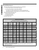
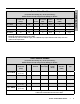
Point-of-Use Models GENERAL INFO (For potable water heating only. Not for space heating.) NOTICE: Models sorted by Voltage, then by Wattage per Element. Model Recommended Breaker Size Voltage (Amps) * † ‡ Number Wattage Current per of per Element Breaker Elements (KW) (Amps) Recommended Wire Size* (AWG) Element Type *P**-40-Y5 20 277 1 4 14.44 12 Single *P**-60-Y5 25 277 1 6 21.66 10 Single *P**-73-Y5 30 277 1 7.3 26.35 10 Single *P**-90-Y5 40 277 1 9 32.
GENERAL INFO Four-Chamber Models (Single Phase) For potable water heating only. Not for space heating. NOTICE: Models sorted by Voltage, then by Wattage per Element. Model Recommended Breaker Size Voltage Number of Elements Wattage per Element (KW) (Amps) Current per Breaker (Amps) Recommended Wire Size* (AWG) *4**-280-X5 70 amps each (2 cirucits) 208 4 7 67.31 6† Single *4**-180-E5 40 amps each (2 circuits) 240 4 4.5 37.50 8 Single *4**-220-E5 50 amps each (2 circuits) 240 4 5.
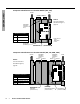
INSTALLATION Getting Started electrical wires that will enter the heater from the side. Clearances Bottom Clearance: At a minimum, maintain a bottom clearance of 8 inches (20.3 cm) for single chamber models or 15 inches (38.1 cm) for 2- or 4-chamber models. Do not store any items underneath the water heater. See Figure 1 or Figure 2. Top Clearance: A minimum of 12 inches (30.5 cm) is required for removal and maintenance of heating elements and to provide access for plumbing connections. Figure 1.
clearances are observed. Do not store any items underneath the water heater, and do not store flammable liquids or other flammable materials near the water heater. This is important for safety and future service. See “Clearances” on page 11. Do not install your water heater underneath condensate lines. • A drain pan, or other means of protection against water damage, is recommended to be installed under the water heater in case of leaks.
the heater. The second wrench must be used to hold the heater’s fittings securely because they are designed to turn freely. Flexible water supply hoses are recommended for your installation. • Well water must be treated. • Only potable water can be used with this water heater. Do not introduce pool or spa water, or any chemically treated water into the water heater. • Do not connect to a saltregenerated water softener or a water supply of salt water.
(ampacity) and circuit breaker ra ng/type are correct for this water heater. model. (See “Wiring Diagrams” on page 29.) If you marked the board and connector during earlier steps, align the marks when plugging the connector in. NOTICE: The electrical requirements for your model are listed in “Electrical Requirements” which starts on page 8. INSTALLATION 4. 1. Connect the electrical service as described in “Electrical Requirements” (starting on page 8). Do the following: B.) Disconnect the plug.
OPERATION Water Temperature Adjustment WARNING Scalding Risk This water heater can make water hot enough to cause severe burns instantly, resulting in severe injury or death. Before a emp ng to adjust the temperature set point, read “RISKS DURING OPERATION” on page 3. If the instruc ons are not clear, contact a qualified service technician. To adjust your temperature se ng, refer to one of the following procedures. turn the temperature adjustment knob as described below.
To toggle between Fahrenheit and Celsius, Figure 7. Two and Four Chamber Models Only: 1. Press and hold the DOWN button for five seconds. See Figure 7. 2. The °F or °C LED will illuminate, and the 7-segment LED will display the temperature set point in the appropriate units.
TROUBLESHOOTING Error Codes for Point-of-Use Models If you have a two- or four-chamber model, see page 19. WARNING Electric Shock Risk Contact with the electrical parts inside the water heater can result in severe injury or death from electrical shock: • Disconnect power by opening the circuit breaker(s) or removing the fuses before installing or servicing. • Some models are connected to more than one branch circuit, and more than one disconnect switch may be required to de-energize the equipment.
Flash Code Sequence Description 18 Moisture detected Shut off all power to the water heater. Check for water leaks. Correct any leaks found. Dry the control board completely before restoring power. 21 Level Detect Ensure that the heater is filled with water and that there is no air trapped inside. Check the opera on of back flow preventer or check valve. If the heater is filled and there are no leaks, connect level detect spades on the circuit board to ground.
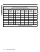
Error Codes for Two and Four Chamber Models If you have a point-of-use model, see page 17. WARNING Electric Shock Risk • Contact with the electrical parts inside the water heater can result in severe injury or death from electrical shock: • Disconnect power by opening the circuit breaker(s) or removing the fuses before installing or servicing. • Some models are connected to more than one branch circuit, and more than one disconnect switch may be required to de-energize the equipment.
Display Description E14 4-Chamber models only: Outlet thermistor open (TH-4). E20 Inlet thermistor shorted. E21 Shorted thermistor. E22 Action / Solution 1. 2. 3. 4. 5. Turn off power to the water heater. Check the connec ons of the thermistor in ques on. Disconnect the thermistor, then reconnect it. Turn on power to the water heater. Does the error code reoccur? If yes, turn off power and replace the thermistor that is listed in the le -hand column.
General Troubleshooting The following chart provides an overview of basic troubleshooting. Symptom Unit “clicks” periodically when no hot water is being used. Hot water supply is warm, but it does not get hot. Hot water temperature fluctuates. Corrective Action Cold water used causes reverse flow through water heater. Install check valve on outlet. Unit has been in standby for an extended period with no hot water use. NORMAL OPERATION.
SERVICE WARNING! Electric Shock Risk Servicing should be performed on this water heater only after it has been disconnected from the power supply circuit(s). Failure to do so can result in severe injury or death from electrical shock: • Disconnect power by opening the circuit breaker or removing the fuses before installing or servicing. • Some models are connected to more than one branch circuit, and more than one disconnect switch may be required to de-energize the equipment.
5 Remove the heater’s front cover, then place a bucket under the water heater to catch any water that spills. NOTICE: If you have a two- or four-chamber model, you must unplug the cover’s ribbon cable from the control board. When you plug it back in later, it must be oriented correctly. (See Figure 5, page 14.) We recommend marking the connector and board with a marker. You will then be able to align the marks. • If you have a point-of-use water heater, go to step 6.
C.) Secure the element by installing and tightening the retaining nut (Figure 14, page 23). Do not overtighten. D.) Secure the red and black wires onto the top of the heating element. Use the two screws that you removed earlier. E.) Reconnect the green ground wire to the element’s ground terminal (flag terminal). 6.5 Reassemble the point-of-use water heater: A.) Reposition both grommets as shown in Figure 17. Ensure that their flat surfaces press firmly against the top plate when you reinstall it.
7.3 Install the new element: A.) Insert the new element into its water heater opening. Make sure that the O-ring is positioned properly. (See Figure 20.) Figure 20. 11 A.) Two- or four-chamber water heaters only: Take the connector end of the cover’s ribbon cable and plug it into the control board. (Plug it in where you see two rows of header pins close together, five pins in each row.) If necessary, refer to the “DISPLAY” callout in the wiring diagram for your model. (See “Wiring Diagrams” on page 29.
Figure 22. Thermistor loca ons (Point-of-use models) OUTLET Figure 24.
5 6 □ □ Remove the thermistor by turning it counter-clockwise with a 1/2-inch open end wrench. Draining the Water Heater Install the new thermistor in the opening by turning it clockwise with a 1/2-inch open end wrench. • Make sure that the O-ring is in place before you install the thermistor. Tighten the thermistor hand tight, then carefully tighten it with a wrench until it is seated. Do not overtighten. Plug the thermistor’s wires into the control board.
Replacement” (page 22). G.) Reinstall the inlet and outlet water lines to the water heater. H.) Go to step 7. Two- or four-chamber water heaters only: 6 Drain the two- or four-chamber water heater: A.) Remove all six screws that secure the access plate beneath the element (at the bottom of the water heater). See Figure 26. Returning the Water Heater to Service circuits, 2.) disconnect the plug, 3.) rotate it 180-degrees, then 4.) plug it back in.
WIRING DIAGRAMS The wiring diagrams for various models are listed in this sec on. Locate the one that corresponds with your model. NOTICE: The correct wiring diagram for your model can be found on the inside of your water heater’s cover. • 1 Chamber, 1 Element, 240/208 VAC (see below). • • 1 Chamber, 1 Dual Element, 240/208 VAC, p. 30. See also “Electrical Requirements” on page 8. • 1 Chamber, 1 Element, 277 VAC, p. 30. • 2 Chamber, 2 Element, 240/208 VAC (other than 16kW, 18kW, or 14kW/208V), p.
1 Chamber, 1 Element, 277 VAC 1 Chamber, 1 Dual Element, 240/208 VAC GRN GRN Level Detect Moisture Sense RED Relay 1 Control Board TH-IN RED RED BLK Element RED BLK TH-AUX BLK 3-Pin Conn. RED BLK Relay 1 RED TH-IN Level Detect Moisture Sense Relay 2 BLK RED RED TH-AUX Relay 1 3-Pin Conn.
Moisture Sense BLK Relay 2 Relay 3 BLK RED BLK RED Relay 1 RED Element 2 Element 1 RED Element 1 BLK BLK BLK Element 2 2 Chamber, 2 Element, 240/208 VAC RED RED Relay 4 BLK Power Supply RED BLK RED TH-IN RED TH-2 RED RED BLK TH-1 BLK Level Detect BLK RED BLK RED BLK GRN Ground Display L1 L2 USE COPPER CONDUCTORS ONLY WHEN CONNECTING TO ELECTRICAL SERVICE. DIAGRAMS NOTICE: 16 kW and 18 kW two-chamber models DO NOT use this configura on.
Moisture Sense BLK Relay 2 Relay 3 BLK RED Relay 1 BLK Element 2 RED Element 1 RED Element 1 BLK BLK BLK Element 2 2 Chamber, 2 Element, 240/208 VAC Used ONLY with the following two-chamber models: • 14 kW at 208V • 16 kW • 18 kW RED RED Relay 4 Power Supply BLK DIAGRAMS BLK RED BLK GRN Ground RED RED BLK RED TH-IN RED BLK RED TH-2 BLK RED BLK TH-1 BLK Level Detect RED L1 BLK L2 RED L1 BLK Display L2 CIRCUIT BREAKER A CIRCUIT BREAKER B USE COPPER CONDUCTORS O
Moisture Sense BLK Relay 2 Relay 4 BLK RED BLK RED BLK RED Relay 1 Element 4 RED Element 3 RED Element 2 RED Element 1 RED Element 1 BLK Element 2 BLK BLK Element 3 BLK BLK Element 4 4 Chamber, 4 Element, 240/208 VAC RED RED Relay 3 Level Detect BLK TH-1 Relay 6 RED Relay 5 BLK RED TH-2 BLK Relay 8 TH-3 RED Relay 7 TH-4 Power Supply BLK RED RED RED BLK RED BLK TH-IN BLK RED RED BLK GRN Ground J7 BLK RED BLK Display L1 L2 L1 L2 CIRCUIT BREAKER A CIRCUIT BREA
APPENDIX: HORIZONTAL MOUNTING OF POU MODELS As stated on page 12, point-ofuse (POU) models may be mounted horizontally. Note the following: • If a POU model is to be mounted horizontally, it must be mounted with brackets (provided). The nipples must face toward the right as shown in Figure 27. • Two-chamber and four-chamber models cannot be mounted horizontally. They must be mounted vertically (nipples facing upward). • This procedure is a supplement to “Mount Your Water Heater,” page 12. Figure 27.
Set the water heater on the brackets, base plate down, and secure it with four sets of bolts and nuts. See Figure 30 and Figure 31. 3 NOTICE: Ensure that the nipples face toward the right as shown in Figure 27, page 34. 4 Return to page 12 to complete the water heater installation. Figure 30. Internal water heater components are represented by hidden lines. DŽƵŶƟŶŐ Surface Water Heater Components Water Heater’s Base Plate Bolts (X4) (Bolt heads face upward) Figure 31.
Copyright © 2018 A.O. Smith Corpora on. All rights reserved.