CONFIDENTIAL T-M50 / T-M50 ASME Service manual Ver. 1.05 T-M50 / T-M50 ASME On-Demand Water Heater Service manual T-M50 A.O.
CONFIDENTIAL T-M50 / T-M50 ASME Service manual Ver. 1.05 Table of Contents 1. Specifications………………………………………...…...………….……………………...………………………… 3 2. Exterior view…………………………………………………………………………………………………………….. 4 3. Interior view….………………………………………………………………………………………………………….. 5 4. List of main components in the interior view……………….……………………………………………. 6 5. Schematic diagram………………………………………………………………………..………………………….. 8 6. Wiring diagram…………………….…………………………………………………………..………………………. 9 7.
CONFIDENTIAL T-M50 / T-M50 ASME Service manual Ver. 1.05 1. Specifications Unit Model T-M50 / T-M50 ASME Unit dimensions H25.3"×W24.8"×D11.8" Weight 102 lbs. Combustion INPUT BTU/h Water control Operation 380,000 Min 15,000 Combustion System Power vent Installation Indoor, Outdoor, Direct vent Fan motor PWM Turbo fan Manifold Pressure* Future Max LP 3.7” WC Natural 2.7”WC LP 0.9” WC Natural 0.7” WC Max Min Flow rate 0.5 to 14.5 GPM Available set temp.
CONFIDENTIAL T-M50 / T-M50 ASME Service manual Ver. 1.05 2. Exterior view Side view Front view 2 4 - 7 / 8" ( 63 2 .9 m m ) 1 2 -1 / 4 " ( 3 1 1 .5 mm ) 4 - 7 /8 " ( 1 2 2 .9 m m ) 25 - 1 / 4" (6 4 2 m m ) 2 - 1/ 2 " ( 6 2 .1 m m ) 2 9 - 7/ 8 " ( 7 5 9 mm ) 1 5 " ( 38 1 m m ) 8 " ( 2 03 m m ) 5" ( 1 2 7 m m ) 1 /2 " ( 1 1 .9 m m ) 1 / 2 " ( 12 .5 mm ) 4 -3 / 8 " ( 1 1 0 .8 m m) GAS 5 - 3 /8 " ( 1 3 7 .
CONFIDENTIAL T-M50 / T-M50 ASME Service manual Ver. 1.05 3.
CONFIDENTIAL T-M50 / T-M50 ASME Service manual Ver. 1.05 4. List of main components in the interior view Items# in No.
CONFIDENTIAL T-M50 / T-M50 ASME Service manual Ver. 1.05 Items# in No.
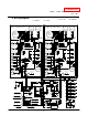
CONFIDENTIAL T-M50 / T-M50 ASME Service manual Ver. 1.05 5. Schematic diagram Output Exhaust Heat Exchanger Heat Exchanger Thermistor Output Thermistor Fan motor Burner Fan motor Gas valve Water control Water control valve vale Flow sensor Inlet Thermistor Mixing Thermistor Flow sensor 120 VAC Gas Hot water Cold water outlet inlet Computer board Inlet Thermistor 1. When a hot water tap is opened, cold water enters the T-M50. 2.
CONFIDENTIAL T-M50 / T-M50 ASME Service manual Ver. 1.05 6.
CONFIDENTIAL T-M50 / T-M50 ASME Service manual Ver. 1.05 7. Wiring diagram check points for diagnosis Checkpoint A A1 Parts and Description 100 V Power supply Color of wires White – Black (A) Brown – Brown (A1) Normal Range 90 to 110 VAC A2,A3 120 V Power supply Black - White 108 to 132 VAC B Igniter Purple – Purple 90 to 110 VAC Light blue - blue at COM (MV) Green - blue at COM (SV1) C Gas valves Orange - blue at COM (SV2) Red - blue at COM (SV3) 78 to 100 VDC (during operation) / 0.9 to 1.
CONFIDENTIAL T-M50 / T-M50 ASME Service manual Ver. 1.05 Checkpoint Parts and Description Color of wires Normal Range 1 to 15 VDC(during operation) H1 Gas proportional valve White - red and 20 to 40 Ω H2 Flow sensor Red - Black 4 to 5.5 VDC White(+) – Black(GND) 1 to 4 VDC (1,200Pulse/min) Yellow – AFR rod Air-fuel ratio rod (Between AFR rod and the computer board) I More than 0.
CONFIDENTIAL T-M50 / T-M50 ASME Service manual Ver. 1.05 8. Resistance values of the temperature thermistors Resistance values at different temperatures Temperature ºF 32 ºC Resistance kΩ Temperature ºF ºC Resistance kΩ 41 0 50 5 59 77 86 95 104 15 20 25 30 15.43 12.56 10.28 8.47 7.02 122 131 140 149 158 167 176 185 194 203 212 50 55 60 65 70 75 80 85 90 95 100 2.16 1.86 1.60 1.39 3.49 2.96 2.53 35 113 19.08 23.76 10 68 40 5.85 4.90 1.21 1.
CONFIDENTIAL T-M50 / T-M50 ASME Service manual Ver. 1.05 9. Operational flow chart Power supply ON FAV&BV open Operation SW ON Remove cause C om p o ne nt s i n t hi s c h ar t s wi t c h fr o m Le f t c om b us t i on s ec t i on t o R ig h t c om b us t i on s ec t i on . Pre-check NORMAL? YES Operation stop B NO B Faucet opens Water Flow Above 0.
CONFIDENTIAL T-M50 / T-M50 ASME Service manual Ver. 1.05 10. Component specifications 10-1. Burners……………………..…………………………………………………..…………………....……… 15 10-2. Gas manifold…………….………………………………………………………..……………………..... 16 10-3. Fan motor………………………………………………………………………...…………………………. 17 10-4. Gas valve assembly……………………………………….…………………………………………….. 18 10-5. Flame rod………………………………………………………….………………………………………… 19 10-6. AFR rod……………………………………………………………………………………………………….. 10-7. Heat exchanger…………………………………………………………….....………………………….
CONFIDENTIAL T-M50 / T-M50 ASME Service manual Ver. 1.05 10-1. Burners Unit Part # #101 AOS Part # EM445 Checkpoint N/A There are 2 types of burners in the water heater: the gas-rich burner stabilizes the flames within the combustion chamber and the air-rich burner Function produces more heat in the combustion chamber. The burners facilitate the air/gas mixture necessary to produce the proper heat during the combustion reaction. 1. Unable to initialize/sustain combustion. 2.
CONFIDENTIAL T-M50 / T-M50 ASME Service manual Ver. 1.05 10-2. Gas manifold Included Unit Part # in #114 AOS Part # EM302 (LP model) EM303 (NA model) Checkpoint N/A 1. The manifold distributes gas from the gas valves to the burners. The manifold has two types of the nozzles: one type for gas-rich burners (16 Function nozzles) and the other for air-rich burners (15 nozzles) 2. There are 3 zones within the manifold, to ensure efficient combustion operation. 1. Dust deposit on the manifold. 2.
CONFIDENTIAL T-M50 / T-M50 ASME Service manual Ver. 1.05 10-3. Fan motor Unit Part # Function #416 AOS Part # EKK25 Checkpoint G To provide combustion air into the combustion chamber and to exhaust flue gas. 1. Fan speed failure, causing abnormal sounds with or without combustion during operation. Failure event 2. Unexpected activation caused by the connectors of the fan motor getting wet. 3. Disconnects from the bottom of the combustion chamber. 1.
CONFIDENTIAL T-M50 / T-M50 ASME Service manual Ver. 1.05 10-4. Gas valve assembly Unit Part # Function Included EM302 (LP model) AOS Part # in #114 EM303 (NA model ) Checkpoint C,H1 Opens and closes the gas pathways of the water heater (main and solenoid gas valves) Modulates the gas flow from the gas inlet (proportional gas valve) 1. Gas leak from the valves. Failure event 2. Unable to open/close (main and solenoid gas valves) 3. Unable to modulate the gas flow (proportional gas valve) 1.
CONFIDENTIAL T-M50 / T-M50 ASME Service manual Ver. 1.05 10-5. Flame rod Unit Part # #103 AOS Part # EKK0E Checkpoint I To detect flames while the water heater is in operation. Function 1. Unable to detect flames when flames actually do occur 2. Detecting a false flame when no flames actually occur 1. The water heater stops operating. The "111" and/or "121" error code(s) Effects on the water will display. heater if flame rod fails 2. The water heater will not initiate the ignition process.
CONFIDENTIAL T-M50 / T-M50 ASME Service manual Ver. 1.05 10-6. AFR rod Unit Part # #103 AOS Part # EKK0E Checkpoint I -Checks flame conditions during combustion. -When AFR rod detects unexpected flame conditions, the computer of the water heater makes adjustments in the fan motor speed to compensate. 1. Unable to detect flames when flames actually do occur Failure event 2. Detecting a false flame when no flames actually occur 1. The water heater will not initiate the ignition process.
CONFIDENTIAL T-M50 / T-M50 ASME Service manual Ver. 1.05 10-7. Heat exchanger EM308 (Regular model) Unit Part # AOS Part # Checkpoint N/A EM323 #444 (ASME model) (ASME model) Absorbs heat from combustion and transfer it to water through the heat Function exchanger pipes. 1. Clogged heat exchanger fins and/or cracks on the heat exchanger walls. Failure event 2. Leaking exhaust gas. 3. Improper heat transfer can cause the water in heat exchanger to boil. 1.
CONFIDENTIAL T-M50 / T-M50 ASME Service manual Ver. 1.05 10-8. Flow sensor Unit Part # #421 AOS Part # EKH33 Checkpoint H2 Detects and measures water flow rate using a spinning impeller and magnetic pick-up. Unable to detect or measure any water flow rate. Function Failure event Effects on the water heater if flow sensor Ignition sequence does not start (water heater will not initiate any operation) fails Error codes when the 441 (only within Easy-link and Multi-unit systems) flow sensor fails 1.
CONFIDENTIAL T-M50 / T-M50 ASME Service manual Ver. 1.05 10-9. Water control valve (flow adjustment valve and bypass valve) Unit Part # #418 AOS Part # EKH32 Checkpoint J The water control valve in the water heater has three functions of water control: flow adjustment, bypass, and two-way) This valve is exactly the same as the water valve in the T-M32. Its functions are as follows: 1. Controls water flow to properly control the output hot water temperature.
CONFIDENTIAL T-M50 / T-M50 ASME Service manual Ver. 1.05 Blue-Brown Function 13.0 to 16.0 VDC Orange-Brown ON: 12.5 to 16.0 VDC OFF: 0 to 1 VDC Red-Brown (0° position) 1 VDC less 3-3/ 8" (8 7mm) 3 - 3 / 4 " ( 9 5 .6 m m ) The water control valve contains the flow adjustment valve and the5bypass - 3 / 8 " valve.
CONFIDENTIAL T-M50 / T-M50 ASME Service manual Ver. 1.05 10-10. Thermistors #424 (Inlet) Unit Part # EKK38 (Inlet) #405 (Output) AOS Part # #430 (Mixing) E1 (Mixing) EKK2T (Output) Checkpoint E2 (Output) EKK1A (Mixing) E3 (Inlet) Function Measures cold / hot water temperatures in the water heater. Failure event Unable to properly measure water temperatures within the water heater. If the thermistors fail open or short, error code appears before starting operation.
CONFIDENTIAL T-M50 / T-M50 ASME Service manual Ver. 1.05 10-11. Hi-limit switch Unit Part # #403 AOS Part # EKN34 Checkpoint C1 -Based on bi-metal thermal expansion. -Detects excessively high water temperature (more than 194˚F or 90˚C) in pipes of the heat exchanger. Function -After detection, communication between the computer board and gas valves are severed, shutting down the water heater instantly. The "111" or "121" error codes will display. 1.
CONFIDENTIAL T-M50 / T-M50 ASME Service manual Ver. 1.05 10-12. Overheat cutoff fuse Unit Part # Function Failure event #402 AOS Part # EK333 Checkpoint C2 The over heat cutoff fuse contains solder with a melting point of 430˚F (221˚C). Detects excessive temperatures within the water heater, especially around the heat exchanger and combustion chamber. Upon detection, communication between the computer board and gas valves will sever, shutting down the water heater instantly.
CONFIDENTIAL T-M50 / T-M50 ASME Service manual Ver. 1.05 10-13. Freeze protection heaters #408 Unit Part # #425 #426 EKN86 EX001 AOS Part # EX002 #441 Checkpoint L EKN67 Prevents the heat exchanger, water valves, and water pipes within the water heater from freezing. The heaters are but one of the freeze protection devices in the water heater. Open circuit failure: ceramic heaters do not receive the voltage needed to Failure event heat up.
CONFIDENTIAL T-M50 / T-M50 ASME Service manual Ver. 1.05 10-14. Left/right computer boards Unit Part # Function Failure event #701 AOS Part # EM306 Checkpoint N/A Controls most of the functions of the left & right combustion sections within the water heater. Malfunctioning computer When this computer board fails, the control from this computer and/or communication to the multi-system control will be abnormal. The following are the typical examples of when the computers fail: 1.
CONFIDENTIAL T-M50 / T-M50 ASME Service manual Ver. 1.05 10-15. Central computer boards Unit Part # Function Failure event #702 AOS Part # EM307 Checkpoint N/A 1. Controls the left/right computer boards for burner control. 2. Sets the installation type (indoor, outdoor, or direct-vent) using dipswitches. 3. Controls multi-unit systems including the Easy-link system. 4. Sets the output temperature of the water heater without the use of a remote controller. 5.
CONFIDENTIAL T-M50 / T-M50 ASME Service manual Ver. 1.05 10-16. Transformer Unit Part # #718 AOS Part # EM296 Checkpoint A1,A2 -To transform input voltage from 120 to 100 VAC. -Every electrical component of the water heater is designed to only work Function with a 100 VAC power supply, therefore, the water heater comes equipped with this transformer. 1. There is no power coming from the transformer. Failure event 2. The voltage from the power supply cannot be converted to 100 VAC. 1.
CONFIDENTIAL T-M50 / T-M50 ASME Service manual Ver. 1.05 10-17. GFI Unit Part # #720 AOS Part # EM207 Checkpoint A,A1 -Detects electrical leakage in the water heater. -Stops providing power to the water heater in the case of electrical leakage. 1. ON-failure: Always in the ON mode (never trips). Failure event 2. OFF-failure: Always in the OFF mode (always stays tripped). 1. ON-failure: GFI cannot detect electrical leakage within the water heater. Effects on the water 2.
CONFIDENTIAL T-M50 / T-M50 ASME Service manual Ver. 1.05 10-18. Igniter Unit Part # #102 AOS Part # EKN74 Checkpoint B -To ignite the gas/air mixtures when the water heater is ready to burn gas on its burner surface. -The output voltage of the igniter is more than 14 kVDC. 1. Unable to ignite during the ignition process. Failure event 2. Makes attempts to ignite at all times. 1.
CONFIDENTIAL T-M50 / T-M50 ASME Service manual Ver. 1.05 10-19. Freeze protection thermostat Unit Part # #140 AOS Part # EM286 Checkpoint N/A Temperature detecting device which prevents the pipes within the water heater from freezing. When this device detects temperatures below 36.5˚F Function (2.5˚C) inside the water heater, power is supplied to the electric heaters to prevent the water heater from freezing. 1.
CONFIDENTIAL T-M50 / T-M50 ASME Service manual Ver. 1.05 10-20. Surge box Unit Part # #722 AOS Part # EM385 Checkpoint A2,A3 Protects the unit from high voltage and/or high electric current caused by lightning. Function There are 2 types of surge absorbers in the Water heater. Surge absorber A is activated by voltage higher than 220 V, the other one is activated by voltage higher than 680 V. 1. Open-failure of the absorber and/or fuse. Failure event 2. Short-failure of the absorber. 1.
CONFIDENTIAL T-M50 / T-M50 ASME Service manual Ver. 1.05 11. Fault Analysis & Specifications Remarks: 1. Proper range of values of voltage & resistance shown below. 2. Please refer to the wiring diagram for checkpoint positions. 3. Remove power to water heater when checking for continuity, disconnections, resistance values, etc. 4.
CONFIDENTIAL T-M50 / T-M50 ASME Service manual Ver. 1.05 Natural of Fault Diagnosis Checkpoint ・The hot water is not 5 Check whether or not the unit is frozen. available when a fixture 6 Check if there is enough gas in the tank / cylinder. (for propane units) is opened ・The hot water turns cold 1 Check whether the flow rate is high enough to keep the water heater running. and stays cold 2 Check if there is a recirculation system installed and check also if the recirculation line has enough check valves.
CONFIDENTIAL T-M50 / T-M50 ASME Service manual Ver. 1.05 Natural Fault of Diagnosis Checkpoint ・ Fluctuation 4 Fault of Left and/or Right PCB of hot water [1] No voltage to gas solenoid valve (SV1). Normal: 78 to 100 VDC between COM (blue) & #9 (green) temperature (during operation) [2] No voltage to gas solenoid valve (SV3). Normal: 78 to 100 VDC between COM (blue) & #73 (red) (during operation) 5 Gas solenoid valve (SV 1) fault [1] Disconnected wiring to gas solenoid valve (SV1) Normal: 1.3 to 1.
CONFIDENTIAL T-M50 / T-M50 ASME Service manual Ver. 1.05 Error Code 101 Error Code Diagnosis 8 Check if there is dust and lint in burner and heat exchanger, when the water heater has been installed in laundry room. 9 Check if there is grease and dirt in burner and fan motor, when the water heater has been installed in restaurant. 10 Check the manifold pressure in the water heater.
CONFIDENTIAL T-M50 / T-M50 ASME Service manual Ver. 1.05 Error Code 111 Error code is shown after three failed attempts at ignition Error Code Diagnosis Checkpoint 7 Inspect flame rod [1] Check for any soot on the rod. [2] Check the connection of ground wire; make sure there is firm contact to the ground of the water heater. (in this case, the wire is contacted to the manifold surface.
CONFIDENTIAL T-M50 / T-M50 ASME Service manual Ver. 1.05 Error Code 121 Error code is shown after three failed attempts at ignition Error Code Diagnosis 5 Disconnected/damaged O.H.C.F. (Refer to section 10-12) V isual inspection: connection/breakage of wires. Normal: 1 Ωor less between blue & blue 6 Check if hi-limit switch is properly functioning. C2 7 Disconnected/damaged hi-limit switch. (Refer to section 10-11) V isual inspection: connection/breakage of wires.
CONFIDENTIAL T-M50 / T-M50 ASME Service manual Ver. 1.05 Error Code Malfunction description Disconnected AFR rod 391 Error Code Turn off the power or water supply Diagnosis Error Code 510 Checkpoint 1 AFR rod fault (Refer to section 10-6) V isual inspection: connection/breakage of wires, soot on it.
CONFIDENTIAL T-M50 / T-M50 ASME Service manual Ver. 1.05 Error Code 551 Malfunction description Cancellation method Fault of driving circuit for any of the gas solenoid valves (SV1, SV2, and/or SV3) Turn off the power supply (The computer checks the condition of the solenoid valves 6 hours after every operation) Diagnosis Checkpoint 1 Left and/or Right PCB and/or gas valve fault (Refer to section 10-4 & 10-14) V isual inspection of gas valves: connection/breakage of wires.
CONFIDENTIAL T-M50 / T-M50 ASME Service manual Ver. 1.05 Error Code Malfunction description Pump failure 631 Cancellation method Turn off the power Diagnosis Checkpoint 1 Check whether the pump connected to central computer board works properly.
CONFIDENTIAL T-M50 / T-M50 ASME Service manual Ver. 1.05 Error Code 701 Error Code Malfunction description 1 Fault of Left and/or Right PCB [1] Fault of preparation for the mixing thermistor operation. Turn off the power or water supply [2] Fault of driving circuit for Gas Proportional Valve(VG0) Diagnosis Checkpoint 1 Check the PCB and/or gas proportional valve (Refer to section 10-4, 10-14 and 10-15) V isual inspection PCB: connection/breakage of wires and/or burn marks on the computer board.
CONFIDENTIAL T-M50 / T-M50 ASME Service Manual Ver. 1.05 Error Code 761 Malfunction description Cancellation method Restoring proper cable connections between all the water heaters and the multi-unit controller (TM-MC01). When Miscommunication between Parent and Child the computer detects proper connections units for Easy-Link systems. between the multi-unit controller and the units (water heater), "761" error code will cease to display.
CONFIDENTIAL T-M50 / T-M50 ASME Service Manual Ver. 1.05 12. Controls and settings 12-1. Diagnosis using the remote controller…………………….…….……...……………………………….……………… 48 12-2. Displaying error codes……………………………………………………………………………………………..…………….. 51 12-3. The error-code button: Verifying functionality of computer board, Displaying error code history, and Clearing error code history memory…………….………………………………………………..…… 54 12-4. Clearing the “101” and “991”error code………………………………………………………………….…………..… 55 12-5.
CONFIDENTIAL T-M50 / T-M50 ASME Service Manual Ver. 1.05 12-1. Diagnosis using the remote controller < Individual unit> 1. Press the "HOT" button and the "COLD" button simultaneously for at least 5 seconds to enter “Diagnostic mode”. “TIME” Button “HOT” “COLD” Button Button 2. "1" will be displayed on the remote controller. (See Fig. 1) In this condition, “1” means the left side combustion section and “2” means the right side combustion section.
CONFIDENTIAL T-M50 / T-M50 ASME Service Manual Ver. 1.05 < For multiple units in the Multi-unit system and the Easy-Link system > 1. Press and hold the "HOT" and "COLD" buttons simultaneously for at least 5 seconds to enter “Diagnostics Mode”. 2. "0" will be displayed on the remote controller. (See Fig. 1) 3. Scroll to the desired T-M50 unit # in the multi-unit system or the easy-link system by pressing the "HOT" or the "COLD" buttons to scroll up or down.
CONFIDENTIAL T-M50 / T-M50 ASME Service Manual Ver. 1.05 Description of mode numbers in “Diagnostics Mode” Mode # 1 2 3 4 5 6 7 8 9 10 Whole multi-unit system information (#0) Total system rate 0 to 9,999 (×0.
CONFIDENTIAL T-M50 / T-M50 ASME Service Manual Ver. 1.05 12-2. Displaying error codes If the T-M50 is undergoing abnormal conditions, the computer will display the error code to indicate the source of the problem. The error codes are displayed on the 7-seg LED of the central computer board and on the remote controller. Please note that error codes are displayed differently, depending on where its being read, and whether it is a single-unit installation or a multi-unit installation. A.
CONFIDENTIAL T-M50 / T-M50 ASME Service Manual Ver. 1.05 B. With easy-link system installations: Example: If Unit #2 fails on the “321” error (inlet thermistor). See the picture below. Central computer board of the Parent unit: In this example, the 7-Seg LED on Parent unit will display “3”…. “2”…. “1”….“0”….”2”, displaying only one digit at a time. The first 3 numbers indicate the error code. The last two numbers indicate that Unit #2 has the error.
CONFIDENTIAL T-M50 / T-M50 ASME Service Manual Ver. 1.05 C. With multi-unit system installations: Example: If Unit #2 fails on the “321” error (inlet thermistor). See the pictures below. Central computer board: The unit that has the error in the multi-unit system will display the error code on its 7-Seg LED in exactly the same way as if it were only a single Unit. So, in this example, the 7-Seg LED on Unit #2 will display “3”…. “2”…. “1”, just like in the single-unit example above.
CONFIDENTIAL T-M50 / T-M50 ASME Service Manual Ver. 1.05 12-3. The error-code button: Verifying functionality of computer board, Displaying error code history, and Clearing error code history memory The T-M50 has the “Error-call button” on the central computer board that provides three main functions listed below. The button is located next to the 7-seg LED (as shown in the picture to the right). Error-call button 7-seg LED A. Check if the computer board works properly 1.
CONFIDENTIAL T-M50 / T-M50 ASME Service Manual Ver. 1.05 12-4. Clearing the “101” and “991” error code The “101” and “991” error codes signify imperfect (abnormal) combustion, caused by insufficient intake air and/or obstructions in the exhaust. A. If the “101” and “991” error code occurs, please check the following: 1. What is the gas-type of the water heater: liquid propane or natural gas? 2. How long has the water heater been installed and been in use? 3.
CONFIDENTIAL T-M50 / T-M50 ASME Service Manual Ver. 1.05 12-5. AFR rod function The AFR rod checks flame conditions during combustion. When the AFR rod detects unexpected flame conditions, the computer board of the T-M50 adjusts the fan motor speed to ensure that air and fuel are always at a proper mixture ratio, minimizing emissions. (Unit: μA) Gas type LPG Installation Natural gas Outdoor Indoor Direct vent Outdoor Indoor Direct vent Combustion MAX 7.
CONFIDENTIAL T-M50 / T-M50 ASME Service Manual Ver. 1.05 12-6. Dipswitch settings of the left/right computer boards The T-M50 shares the computer board with the T-M50 ASME. There is a bank of dipswitches on the T-M50’s left & right computer boards. The dipswitch functions are shown on the following table but generally do not need adjustment. Carefully verify the function of each dipswitch before changing any settings.
CONFIDENTIAL T-M50 / T-M50 ASME Service Manual Ver. 1.05 12-7. Dipswitch settings of the central computer board There are two banks of dipswitches (upper and lower) on the central computer board. The dipswitch functions are shown on the following table. Carefully verify the functions of each dipswitch before changing any settings. Changing dipswitches from the factory default settings may damage the T-M50 and the system.
CONFIDENTIAL T-M50 / T-M50 ASME Service Manual Ver. 1.05 The functions of the lower dipswitch bank No. Functions and Dipswitch settings 1 Output temperature settings 2 (See table to the right) 3 (Default 120°F) No.
CONFIDENTIAL T-M50 / T-M50 ASME Service Manual Ver. 1.05 12-8. Assigning unit numbers in the Easy-link system A. How to display the unit number Press the “Unit # display” button on central computer board. The 7-seg LED will then display the assigned number for that T-M50 unit for 10 sec. NOTE: In a single-unit installation, the numbering system is disabled. B. How to reset and reconfigure the numbering of units Unit #’s can be reset and reassigned manually: 1.
CONFIDENTIAL T-M50 / T-M50 ASME Service Manual Ver. 1.05 12-9. (A) ON/OFF conditions: Overview The following table shows the ON/OFF conditions of the water heater. For Every pump modes ON/OFF Conditions The BTU requirement is more than 11,900 BTU/h AND Conditions needed to turn ON. The water flow rate is more than 0.5 GPM The BTU requirement is less than 5,950 BTU/h OR Inlet temperature is higher than the set Conditions needed to turn OFF.
CONFIDENTIAL T-M50 / T-M50 ASME Service Manual Ver. 1.05 12-9. (B) ON/OFF conditions: BTU requirements A. Calculating the ON/OFF conditions of the T-M50 【Condition needed to turn the T-M50 ON】 (Tset – Tin) × GPM × 500 > 11,900 【Condition needed to turn the T-M50 OFF】 (Tset – Tin) × GPM × 500 < 5,950 or Tin = Tset Where: Tset = Output set temperature and Tin = Inlet temperature B. Calculation example Set temperature: Tset = 120˚F Flow rate = 2.
CONFIDENTIAL T-M50 / T-M50 ASME Service Manual Ver. 1.05 12-10. Conditions that stop the T-M50 from operating The T-M50 contains two combustion sections (left and right). The section(s) that fire on at any given time will depend on the flow rate and set temperature of the T-M50. This dual combustion or redundant system improves the T-M50’s dependability if abnormalities or error codes occur.
CONFIDENTIAL 12-11. Pump control ON/OFF Conditions T-M50 / T-M50 ASME Service Manual Ver. 1.05 To run circulation pumps efficiently and effectively, the T-M50 offers four different modes of pump control. The following table shows the pump control ON/OFF conditions for different modes. To change pump control modes, see section 12-7 for dipswitch settings. “Normal mode” and “Storage tank circulation mode” There are no specific ON/OFF conditions for these two modes.
CONFIDENTIAL T-M50 / T-M50 ASME Service Manual Ver. 1.05 12-12. Multi-unit system ON/OFF conditions In Easy-link system and Multiple-system, the amount of T-M50 called on to activate depends on the FLOW RATE and the OUTPUT SET TEMPERATURE. 1. Condition required to activate an additional T-M50: Flow rate required to activate additional T-M50 = A × n Where n= number of currently activated T-M50’s (One T-M50 has two combustion sections.) and A is dependent on the output set temperature.
CONFIDENTIAL T-M50 / T-M50 ASME Service Manual Ver. 1.05 3. Example: Output set temperature = 120˚F in a four-unit system and priority unit is No. 1 (See the table below) 1 2 3 T-M50 4 5 T-M50 T-M50 To activate additional T-M50’s 7 8 T-M50 To reduce number of activated T-M50’s Flow rate Combustion unit No. 6 GPM L/min Flow rate Combustion unit No. GPM L/min No.1 ON 0.5 1.9 No.1+2+3++4+5+6+7+8 OFF 19 72 No.1+2 ON 3 12 No.1+2+3+4+5+6+7 OFF 16 60 No.1+2+3 ON 6 24 No.
CONFIDENTIAL T-M50 / T-M50 ASME Service Manual Ver. 1.05 12-13. Operation time for unit rotation The T-M50 contains two combustion sections. The section that turns on first is whichever section the T-M50 decides is the primary section. The priority unit and section will rotate when it reaches 100 ON/OFF cycles or after 12 hours of operation. NOTE: The priority unit and section is the unit that turns on first when there is a hot water demand.
CONFIDENTIAL T-M50 / T-M50 ASME Service Manual Ver. 1.05 12-14. Individual unit operation in multiple-system while multi-unit controller (TM-MC01) is under abnormal conditions (Individual operation mode) A multi-unit system of T-M50s requires the multi-unit controller. If the multi-unit controller undergoes abnormal conditions, the T-M50s can operate as individual units. If this happens, the minimum flow rate of the system changes from 0.5 GPM to 0.5 GPM multiplied by the number of T-M50s.
CONFIDENTIAL T-M50 / T-M50 ASME Service Manual Ver. 1.05 12-15. High-Altitude Region Support Functions (FM+, FM++, FM+++ and INPUT-) Left/right computer boards <Using this function> The high-altitude region support functions have four operation levels, with the appropriate level being set up by the installer until the abnormal sound problem is solved. The desired level can be specified at the left bank of dipswitches (No.1 and No.8) on the computer board.
CONFIDENTIAL T-M50 / T-M50 ASME Service Manual Ver. 1.05 12-16. Alarm port terminal This function is to alert end-users of any error codes that may occur by using an alarm lamp and/or the buzzer and connecting it to the central computer board. When the left/right computer(s) and/or the central computer board detect any error codes, the alarm port terminal on the central computer board will turn ON, activating the connected lamp or buzzer.
CONFIDENTIAL T-M50 / T-M50 ASME Service Manual Ver. 1.05 12-17. How to use the “External fan control” (Only on Parent Unit) The external fan is needed when the air in the room is not enough for the combustion. T-M50 external fan motor terminals are a terminal to connect to the external fan motor. This terminal turns ON before the T-M50 start to burn. A draft pressure switch setting is also recommended in order to check if the external fan motor works correctly.
CONFIDENTIAL T-M50 / T-M50 ASME Service Manual Ver. 1.05 12-18. Relay selection for the pump control connection The maximum current capacity of the T-M50’s pump control connection in the central computer boar is 1 amp. Before using relay with the pump control, please check the specifications of that particular relay to ensure that the current value through the coil will not exceed 1 amp. For example To the right, there is a sample of relay specifications from an arbitrary brochure.
CONFIDENTIAL T-M50 / T-M50 ASME Service Manual Ver. 1.05 12-19. Adjusting manifold gas pressure The manifold gas pressure on the T-M50 can be adjusted by following the procedures below. WARNING Adjusting the manifold pressure can cause unexpected combustion conditions during operation, which can cause a health hazard, damage the T-M50, and/or shorten its lifespan. Therefore, changing the manifold pressure is not recommended unless there are very strong reasons to do so (e.g.
CONFIDENTIAL T-M50 / T-M50 ASME Service Manual Ver. 1.05 5. Press and hold down the “MIN” button on the computer board. While holding down the “MIN” button, press either the “Increase” or “Decrease” button to increase or decrease the manifold gas pressure, respectively (Figure 3). Refer to the manometer to verify that pressure has been set to desired value. 6. When the minimum gas pressure of the combustion unit is being adjusted, the combustion of the other combustion unit must be set to MINIMUM. 7.
CONFIDENTIAL T-M50 / T-M50 ASME Service Manual Ver. 1.05 12-20. Manually adjusting the fan motor speed While the FM+ dipswitch will automatically increase the fan speed by 6%, the fan motor speed on the T-M50 can also be manually adjusted. In order to perform manual adjustments to the speed, a remote controller is required.
CONFIDENTIAL T-M50 / T-M50 ASME Service Manual Ver. 1.05 12-21. Freeze protection system There are two features to the T-M50’s freeze protection system: the automatic fan motor system and the ceramic heating blocks. The automatic fan motor system allows the T-M50 to briefly do fan motor operation and the ceramic heating blocks will heat up whatever portion of the heat exchanger the blocks are strapped to.
CONFIDENTIAL T-M50 / T-M50 ASME Service Manual Ver. 1.05 When the computer checks for these temperatures during the fan motor operation as freeze protection, the Automatic fan motor system will deactivate if: Tout > Tin + 3.
CONFIDENTIAL T-M50 / T-M50 ASME Service Manual Ver. 1.05 Automatic firing system Activation conditions will depend on the on whether or it is a direct-vent installation. Gas and electrical power are required for this feature to operate.
CONFIDENTIAL T-M50 / T-M50 ASME Service Manual Ver. 1.05 12-22. Freeze protection for recirculation systems The T-M50 has the freeze protection function for a re-circulation system by using a pump installed in the system. Basically, this function is only ON / OFF control of the pump from the central computer board in the T-M50. When the central computer board detects the potential of the system freezing, the pump in the system starts automatically.
CONFIDENTIAL T-M50 / T-M50 ASME Service Manual Ver. 1.05 12-23. Draining the unit and cleaning the inlet water filter 1. Close the manual gas shut off valve. 2. Turn off power to the T-M50, wait a few seconds. And then turn on again. 3. Wait 30 seconds for water valves starts to completely open. Then turn off power to the T-M50, yet again. 4. Close the water shut-off valve. 5. Open all hot water taps in the house. When the all water flow has ceased, close all hot water taps. 6.
CONFIDENTIAL T-M50 / T-M50 ASME Service Manual Ver. 1.05 13. Components diagrams 3 4 12 Case assembly 3 1 3 2 4 10 2 4 3 11 5 8 718 9 3 6 4 7 13 3 Computer board assembly The T-M50 and the T-M50 ASME share the same components.
CONFIDENTIAL T-M50 / T-M50 ASME Service Manual Ver. 1.05 Burner assembly The T-M50 and the T-M50 ASME share the same components.
CONFIDENTIAL T-M50 / T-M50 ASME Service Manual Ver. 1.05 Combustion and Exhaust assembly Other than Part# 444, Part# 445, Part# 446 and Part# 447, the T-M50 and the T-M50 ASME share the same components.
CONFIDENTIAL T-M50 / T-M50 ASME Service Manual Ver. 1.
CONFIDENTIAL T-M50 / T-M50 ASME Service Manual Ver. 1.05 14.
CONFIDENTIAL T-M50 / T-M50 ASME Service Manual Ver. 1.
CONFIDENTIAL T-M50 / T-M50 ASME Service Manual Ver. 1.
CONFIDENTIAL T-M50 / T-M50 ASME Service Manual Ver. 1.
CONFIDENTIAL T-M50 / T-M50 ASME Service Manual Ver. 1.
CONFIDENTIAL T-M50 / T-M50 ASME Service Manual Ver. 1.
CONFIDENTIAL T-M50 / T-M50 ASME Service Manual Ver. 1.05 15. Records of revision of this manual Version Changes Date 1.00 First edition 11/26/07 1.01 Revised by the R&D and Takagi Japan 03/04/08 1.02 Revision of wrong information in section 12-14 07/02/08 1.03 Revised by the R&D and Takagi Japan 08/11/08 1.04 Revised by the R&D and Takagi Japan 02/12/09 1.