
Service manual


T-M50 / T-M50 ASME Service manual
Ver. 1.05
38
CONFIDENTIAL
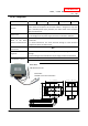
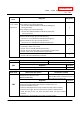
Natural of
Fault
Diagnosis Checkpoint
4 Fault of Left and/or Right PCB
[1] No voltage to gas solenoid valve (SV
1
).
Normal: 78 to 100 VDC between COM (blue) & #9 (green)
(during operation)
[2] No voltage to gas solenoid valve (SV
3
).
Normal: 78 to 100 VDC between COM (blue) & #73 (red)
(during operation)
C
5 Gas solenoid valve (SV
1
) fault
[1] Disconnected wiring to gas solenoid valve (SV
1
)
Normal: 1.3 to 1.9 kΩ between COM (blue) & #9 (green)
[2] Disconnected wiring to gas solenoid valve (SV
3
)
Normal: 0.9 to 1.7 kΩ between COM (blue) & #73 (red)
C
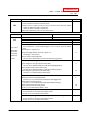
6 Fault of Left and/or Right PCB
No voltage to water control valve
Normal: 13.0 to 16.0 VDC between (blue-brown)
Normal: ON 12.5 to 16.0 V/ OFF 0 to 1 V between (orange-brown)
Normal: 1 VDC less (0˚ position) between (red-brown)
J
・ Fluctuation
of hot water
temperature
7 Fault of Water control valve
Normal: 0.09 to 0.2 kΩ between (red-black)
J
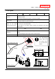
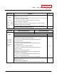
Error Code
Malfunction description Cancellation method
Incorrect dipswitch setting fault Turn off the power or water supply
Diagnosis Checkpoint
031
Check the dipswitch settings on PCBs
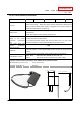
Error Code
Malfunction description Cancellation method
Warning for the “991” error code
(Refer to section 12-4)
On the Left and/or Right PCB, press the
INC and DEC buttons simultaneously for 3
sec. Then turn the power off.
Diagnosis Checkpoint
101
1 Check the gas type of the water heater.
2 Check how long the water heater has been installed and in use.
3 Check the installation location.
4 Check the altitude/elevation of area of where the water heater installed.
5 Check the vent length, when the water heater has been installed indoors.
6 Check the type of vent cap, when the water heater has been installed
outdoors.
7 Check if there is any blockage in the intake air and/or exhaust.