
Service manual

T-M50 / T-M50 ASME Service Manual
Ver. 1.05
52
CONFIDENTIAL
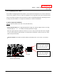
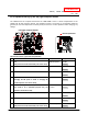
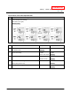
B. With easy-link system installations:
Example: If Unit #2 fails on the “321” error (inlet thermistor). See the picture below.
Central computer board of the Parent unit: In this example, the 7-Seg LED on Parent unit will display
“3”…. “2”…. “1”….“0”….”2”, displaying only one digit at a time. The first 3 numbers indicate the error
code. The last two numbers indicate that Unit #2 has the error.
Central computer board of the unit that has the error: The unit that has the error in the easy-link
system will display the error code on its 7-Seg LED in exactly the same way as if it were only a single
Unit. So, in this example, the 7-Seg LED on Unit #2 will display “3”…. “2”…. “1”, just like in the
single-unit example before.
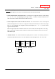
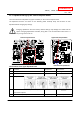
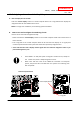
When the right and/or left combustion section has an error code, the red lamp next to the 7-Seg
LED on the central computer board will flash to indicate which combustion section has the error
code. Refer to p.50.
Remote controller: The remote controller will display “232” on its screen in its entirety. The first “2”
indicates that Unit #2 has the error. The “32” indicates the first two digits of the “321” error code.
Remote Controller
Unit #1
PARENT
Unit #2
CHILD
Unit #3
CHILD
Unit #4
CHILD
“3..2..1..0..2”
“3..2..1”
“232”