
Service manual


T-M50 / T-M50 ASME Service manual
Ver. 1.05
9
CONFIDENTIAL
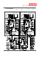
6. Wiring diagram
BK:BLACK
P:PURPLE
LB:LIGHT BLUE
BL:BLUE
G;GREEN
Y:YELLOW
O:ORANGE
BR:BROWN
H
e
a
t
e
r
Thermostat
Inlet
thermistor
Output
thermistor
Mixing
thermistor
BK
BK
BK
GFI
Tra ns-
for mer
1
2 3 4 5 6
O F F
BR
BR
120 VAC
10A
G
Ground
W
BK
BR
Ground
Air-fuel
ratio rod
Ground
Flame
rod
1 2 3 4 5 6
OFF
1 2 3 4 5 6
OFF
MV
SV1
SV2
SV3
Remote
control ler
Parent
W
W
IG
Ground
Ground
Inlet
thermistor
Output
thermistor
Mixing
thermistor
BK
BK
BK
1
2 3 4 5 6
O F F
Air-fuel
ratio rod
Ground
Flame
rod
MV
SV1
SV2
SV3
FM
Igniter
rod
IG
Heater
Heater
Heater
Heater
Heater
7
7
8
8
R
Y
G
W
BK
BL
R
O
Y
G
W
BK
BL
R
Y
G
W
BK
BL
R
O
Y
G
W
BK
BL
Water
Control
valve
Water
Control
valve
B K
B K
B K
B K
BK
BK
BK
BK
Y
G
O
O
G
Y
BK B K
W
W
BL
BK
BK
R
R
BL
BL
GG
R
BL
Y
O
W
P
PP
PP
PP
P
G
WR
BK
W
R
WR
BK
R
W
BL
LB
G
O
R
W
BK
Y
W
BK
W
BK
BL
LB
G
O
R
BK
W
BK
W
W
BK
BK
W
W
W
W
W
W
W
Gas
Porpor-
tional
Valve
Flow
Sensor
WR
BK
W
R
WR
BK
R
W
Hi-
limit
BL
O.H.C.F
BL
BL BL
BL
FM
R
BL
Y
O
W
BL
Hi-
limit
BL
O.H.C.F
BL
BL BL
BL
BL
Flow
Sensor
Left side unit
Right side unit
Surge
box
BK
W
MAX button
MIN button
Increase button
Decrease button
Burning lamp
Communication
lamp (right)
Communication
lamp (left)
Multi-system
on line lamp
Lower bank of
dipswitches
Upper bank of
dipswitches
7 Seg LED
Pump test run
Error call
button
Burning lamp
FM
port
Pump
port
Button to check
unit number
Priority SW
Alarm
contact
Draft switch
Dipswitches
MAX button
MIN button
Increase button
Decrease button
2
1
Dipswitches
Gas
Porpor-
tional
Valve
Igniter
rod
I
F
D1
D2
H1
H1
H2
J
J
E1
E1
E3
E3
E2
E2
C C
A
A
A A
C2
C2
C1
C1
B
B
I
N
M
K
A3
A1
A2
L
L
L
L
L
L
L
G G
TM-RE30
H2