Upsilon Commercial Modular High Efficiency Condensing Boiler UB - 70/110/140 Installation and Service Manual These instructions should be retained by user. 8G.51.91.03/09.13 Changes reserved. E. & O. E. 0310 351 Innovation has a name.
Installation and Service Manual Upsilon-Series Version: from sv 4.
1 2 3 4 5 6 7 8 9 10 11 12 13 14 15 Introduction..............................................................................................................................................4 Regulations.............................................................................................................................................7 Scope of delivery.....................................................................................................................................
1 Introduction These instructions describe the functioning, installation, use and primary maintenance of A.O.Smith central heating boilers for the United Kingdom and Ireland. Where necessary the different regulations for each country are separately described. These instructions are intended for the use of Gas Safe registered installers or registered Bord Gais installers in connection with the installation and putting into operation of A.O.Smith boilers.
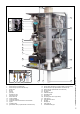
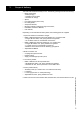
20 19 7 4 T1 6 T1a 3 5 P1 T2 1 21 4 7 6 3 5 2 9 10 14 11 22 15 G 16 C A R 8 13 12 description components 1 2 3 4 5 6 7 8 9 10 11 12 13 14 15 heat exchanger 1 (All UB-types) heat exchanger 2 (UB 110 and UB 140) ignition unit fan unit damper gas valve automatic air vent main switch 230V boiler contol unit control unit MMI connection terminal connection terminal cascade bus communication syphon circulation pump gas isolation valve (in optional boiler connections set) 16 17 18
1 2 14 13 11 12 8 3 4 5 6 7 10 9 description components Installation and Service Manual Upsilon-Series 1 2 3 4 5 6 7 6 Air supply (for parallel flue connection) Flue/Air supply (concentric) Gas isolation valve Service valves flow and return Non-return valve Flow/return header Gas line 8 9 10 11 12 13 14 Low velocity header Safety valve Fill and drain valve Automatic air vent low velocity header Pocket for temperature sensor T10 Cascade manager Frame figure 1.
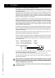
Regulations The following regulations apply to the installation of A.O.Smith central heating boilers: Legislation and Regulations. Gas Safety (Installation and Use) Regulations. All gas appliances must by law, be installed by a competent person, eg. Members of Gas Safe Register and in accordance with the current Gas Safety (Installation and Use) Regulations. Failure to install the appliance correctly could lead to prosecution.
Take note of the following when maintenance or adjustments are needed: - The boiler must be able to function during these activities; for this reason, the boiler’s supply voltage, gas pressure and water pressure must be maintained. Ensure that there is not a source of potential danger during these activities. Following maintenance or other activities; always check the connections of all parts through which gas flows (using leak-search spray).
Scope of delivery The boiler will be delivered ready for use. The delivery package includes the following: • Boiler and housing: • Boiler pump(s); • Cascade control system; • Automatic air vent(s); • Siphon; • Lid ø100 air supply (with screw); • PG cable glands; • Suspension bracket; • Mounting material consisting of plugs and screws; • Installation and Service Manual; • User manual; Depending on the selected cascade systems, the following parts are supplied: 1.
4 Description The Upsilon is a condensing and modulating CH-boiler. The boiler has one or two stainless steel heat exchangers with smooth pipes. A hightec principle with durable materials suitable for room sealed open flue or over pressure cascade flue systems The CH-boiler uses (natural) gas to supply heat. This heat is transferred in the heat exchanger to the water contained in the CH-installation. Severe cooling down of the flue-gases causes condensation.
Installation and mounting Install the boiler in a well-ventilated boiler room in accordance to the actual regulations. The installation location of the CH-boiler(s) has to be, and remain, frost-free. It is NOT necessary to have a purpose provided air vent providing a twin pipe or concentric room sealed flue system is used in the room or internal space in which the boiler is installed.
5.1 Wall-mounted in line A . Position the pipe work header against the wall. When using several pipe work headers: couple the pipe work headers and supplied gaskets, M12 (DN65) or M16 (DN100) bolts, spring washers and nuts. Align the pipe work header(s) horizontally using the adjustable feet. Figure 5.1.a B. Determine the position of the suspension brackets based on figure 5.1.c.
5.2 Free-standing in line A . Position the pipe work header in the required location. When using several pipe work headers: couple the pipe work headers using the supplied gaskets, M12 (DN65) or M16 (DN100) bolts, spring washers and nuts. Align the pipe work header(s) horizontally using the adjustable feet. Figure 5.2.a B. Place the gas line in its intended recess. When using several pipe work headers: couple the gas lines using the supplied DN50/DN65 gaskets, M12 bolts, spring washers and nuts.
5.3 Free-standing back-to-back A. Position the pipe work header in the required location. When using several pipe work headers: couple the pipe work headers with the supplied gaskets, M12 (DN65) or M16 (DN100) bolts, spring washers and nuts. Align the pipe work header(s) horizontally using the adjustable feet. Figure 5.3.a B. Place the gas line in its intended recess. When using several pipe work headers: Couple the gas lines using the supplied DN50/DN65 gaskets, M12 bolts, spring washers and nuts.
5.4 Connecting the boiler A. Remove the remaining packaging part from the bottom of the boiler. Note: this packaging part is provided with boiler parts which are needed for mounting the boiler. Figure 5.4.a B. Cap the connections that are not used on the pipe work headers: Flow and return: Gas: ø35mm blind compression fitting 1 ¼" blind cap with gasket (2 items/boiler) (1 item/boiler) For connections, use the supplied gaskets. Check all connections for leakage and gas-tightness. Figure 5.4.b C.
6 Hydraulic and gas pipe line system 6.1 Heating system Install the CH-system in accordance with present legislation. The pipe work headers are available in 2 dimensions, i.e. DN65 and DN100 and are connected to one another by the flange couplings and gaskets, M12 or M16x55 bolts, spring washers and nuts. The low velocity header and the complete installation can then be connected to it. Figure 6.1.
Required components that are not supplied by A.O.Smith: - The installation pump; - The condensate discharge system. - The installation water filter; - Air and dirt separator - Gas filter; - Hot water supply - Regulation valve; 6.2 Expansion vessel The CH-installation has to be fitted with an expansion vessel. The expansion vessel used has to comply with the water contents of the installation. It is not necessary to install an expansion vessel to each boiler.
- On installation and during additions or changes at a later stage, A.O.Smith recommends to keep a record of the type of water used, its quality at the time, and if applicable, which additives and quantities were added. Parameter Value Water type Potable water Softened water pH 6.0-8.5 Conductivity (at 20°C in µS/cm) Max. 2500 Iron (ppm) Max. 0.
6.4 Gas line Mount the gas line in accordance with present legislation. If required, mark the gas line in accordance with present legislation. United Kingdom: The gas supply must comply to the current Gas Safety, Installation & Use Regulations. Ireland: - Irish standard 813 - Domestic gas installations The gas line leading to the installation has to be calculated to the maximum capacity to determine the diameter of the supply pipe.
6.5 Condensate drain All A.O.Smith wall hung gas fired condensing boilers contain a syphonic condensate trap to collect and release condensate. The amount of condensate formed is determind by the type of boilers and the water temperature produced by the boiler. Figuur 6.5.a Condensate pipework. Press the supplied plastic ribbon tube onto the condensate drain at the bottom of the boiler (fig. 6.5.a).
Final discharge options. The condensate pipe can only terminate into any one of the five areas as shown in the diagrams on this page. Draining of the condensation water to the external rain guttering is not permitted in view of the danger of freezing. Before putting the boiler into operation fill the syphon with 600 ml of water. -Condensate from boiler syphon/trap -Sink with internal overflow -25mm dia. Plastic condensate pipe -External drain or gully -Internal soil and vent stack.
7 Flue gas system The flue gas exhaust system and air supply system consists of: - Flue gas pipe; - Air supply pipe; - Roof or wall terminal. The flue gas exhaust system and air supply system must comply with: United Kingdom: The flue gas outlet and air supply installation must comply with the current regulation requirements. IG UP 10, BS 715 and BS 6644. Ireland: - Irish standard is 813 section 9.10.
7.1 Parallel boiler connection The boiler comes as standard with a parallel connection for the flue gas outlet and air supply system. The air supply opening (1) has a diameter of ø100mm. The air supply channel can be connected to it, or, if it involves an “open device” (Drainage category B), an air filter can be connected (recommended). 1 3 The air supply (3) of the concentric part is closed by a lid ø150mm. 2 Figure 7.1.a The flue gas outlet connection (2) has a diameter of ø100mm. 1430 7.
7.3 Connecting the flue gas outlet-/air supply system Upsilon-boilers can be used both in an “open” and in “closed" system. Open: The required combustion air is taken from the immediate environment (boiler room). For this purpose, please comply with the applicable boiler room ventilation regulations BS 6644. When using boiler category B23 and B33 as an 'open boiler', the protection degree of the boiler will be IPX0D instead of IPX4D. A.O.
Possible warranty claims will not be honoured if incorrect changes result in non compliance with the installation manual or local rules and regulations. The flue gas system should be built up using only A.O.Smith program products. Combinations with other brands or systems are, without written permission from A.O.Smith, not permitted.
The appliance produces a white wisp of condensation (pluming). This wisp of condensation is harmless, but can be unattractive, particularly in the case of outlets in outside walls. At this time there are 2 different ways of connecting the flue gas/air intake system, parallel or concentric. See chapter 7.1 and 7.2 how to convert the boiler connection to the desired option. 100/150 = 350mm Dismantlement and shorten pipes figure 7.4.
7.5 Collective flue gas outlet Opting for a collective flue gas outlet is determined by: - The position of the boilers with regard to their outlet area - Sufficient space above the boilers - Large number of boilers You may opt for: - Collective flue gas outlet under-pressure - Collective flue gas outlet over-pressure In many situations, flue gases cannot be vented individually because the installation is indoors.
7.5.1 Collective flue gas outlet under-pressure Diameter and venting lengths of the flue gas outlet/air supply: Open system, with under-pressure (calculated with thermal draft) Output (P) under atmospheric circumstances. kW at Dimensions cascade flue Upsilon Open system, underpressure 80/60°C d h d NOTE! 1. IPX0D at flue category B23 and B33 Table 7.5.1.
7.5.2 Collective flue gas outlet over-pressure An installation with a collective flue gas outlet over-pressure in combination with individually controlled boilers (e.g. 0-10 V control), where no bus cable 0310289 is connected, is NOT allowed. Diameter and venting lengths of the flue gas outlet/air supply: Open system with over-pressure. Output (P) kW at 80/60°C d h d NOTE! 1. IPX0D at flue category B23 and B33 2. Only with bus cable 0310289 connected! 3. Adjust parameter 102 to 2 Table 7.5.2.
7.6 Condensate vent collective flue gas outlet system Flue gases condensate inside the outlet system. Anticipate approx. 1 litre of condensate per m3 of natural gas spent on heating. The resulting condensate has to be drained. Therefore, collective flue gas outlet systems have to be fitted with a condensate drainage facility. Using a plastic siphon, the drainage is connected to the sewage system by means of an open connection. The diameter of the condensate drainage is 40 mm and may be made of PVC.
8 Electrical connections The appliance complies with the CE Machinery Directive 89/392/EEC. The EC Low Voltage Directive 72/23/EEC and the EC EMC Directive 89/336/EEC. - A 230V -50Hz mains electrical supply is required fused externally at 6,3A. - A deviation on the grid of 230V (+10% or -15%) and 50Hz The installation must continue to comply with: United Kingdom: - the national rules for electrical installations , IEE regulations.
Connection 8X.44.08.00 / 05.11 Position 16 Connections On/Off 230V out N 230V~ AC L 1 N 230V out L 230V~ AC 2 3 4 N L 230V out 5 6 230V Pump P3 7 8 9 N N L L Error signal 230V Pump / 3-WV. 10 11 12 13 On/Off 1, 2, 3 Live 4, 5, 6 Live 7, 8, 9 Live 10 Live 11 Live Heat demand signal L 230V DHW pump 14 15 16 1 2 T4 Out LPG 3 4 5 6 Neutral T3 DHW 1 T10 2 Neutral 3 4 5 6 7 8 Earth 0-10Volt 9 10 Neutral LWCO Earth 11 Live Neutral Earth 2.
4. Bus communication: Position Connection 4-pole connector Application Bus communication cable figure 8.f PG IP67 The 0310289 bus communication cable mutually connects the cascaded boilers by 4-pole connectors on the side of the connection terminals (2 boilers: 1 cable, 3 boilers: 2 cables etc.) and is fitted with 2 IP67 tulles. A maximum of 8 boilers can be connected to the system. 8.1 External controls NOTE: - T10 must be connected - T4 is adviced to connect.
3. 0-10 Volt-control At a heat demand of the 0-10 Volt controller a signal is sent out and varies from 0-10 Volt. This signal is translated by the Upsilon boiler to a set value (desired flow water temperature or load) which is send via the data bus to the boiler(s). Depending on the Voltage the set value becomes higher or lower. On/Off T4 Out T3 W T10 4 5 6 0-10Volt 7 Figure 8.1.c 8 9 10 LWCO 11 12 13 14 The 0-10 Volt-controller must be connected to terminal 3, position 9 and 10.
8.2 Wiring diagram A7 A4 A5 A6 B7 A8 B4 T1 B5 P1 A9 B6 A10 T2 P1 B9 A11 T1a B10 T2 B11 B8 A22 T1a (HEX4) B23 B22 A23 24 A2 1 X7 X8 X9 B2 X12 X11 X1 X6 20 10 X5 30 8 X4 1 12 X3 X8 X9 X12 X11 1 X1 23 20 10 6,3A T 6,3A T B 10 1 X5 1 30 18 9 9 1 X7 X6 X2 18 9 1 1 2 3 6,3A T 6,3A T A 10 1 11 8 1 X2 X4 1 12 X3 1 9 25 B3 1 A20 A21 A3 16 1 C1 14 1 C2 6 1 C3 26 figure 8.1.
Connections Item Art.nr.
Boiler control The boiler has a control unit. This control takes care of most of the manual settings but also provides numerous settings to adjust the control exactly to the installation and user requirements. Display The LCD screen is backlit. The light is activated by pushing one of the buttons. There are 3 light colours available.
9.1 Operational status Standby - Standby - Vent.Phase - Ignition phase - Burner lit CH - Burner lit DHW - CH T > Tset - Overrun CH - Overrun DHW - Service - Frost Standby. Boiler is ready for operation. Ventilation stage Ignition stage Burner active for heating Burner active for hot water Burner off on account of too high flow temperature CH Overrun time pump over CH Overrun time pump over DHW Boiler needs maintenance. Contact installer Burner active for frost protection 9.
9.
The standard read-out offers 3 information screens. Switching to different screen scan be found using the + or - button 1 Good we 10:17 2 1. "Good"- read-out Good with actual day and time (see above) 2. Operational status Refer to chapter 9.1 for explanation of texts 3. Technical read-out Actual water flow temperature. (T1 in °C) and water pressure (P in bar). + OK - Standby 3 20.0 °C 1.
9.4 Setting the maximum flow water temperature with On/Off-control P101 = 0 Setting the maximum flow water temperature with connected outdoor sensor T4 (starting with illuminated display): CH temp 85 °C Timeprog options Timeprog CH Day Temp T_day 85 °C 2. Press the OK button; 3. Press the right arrow button until CH temp: The display shows: CH temp 85°C; 4. Press the + or - button to adjust the desired flow temperature and press the OK button.
9.5 Filling the heating system When all boilers have been electrically commissioned as described above, then the heating system can be filled. Each boiler is fitted with a filling and drain valve. The filling hose from the water tap is then connected to it. Fill the heating system only with drinking water. Refer to the Water Quality chapter for quality requirements of the filling water.
10 Basic settings Menu structure There are 2 setting levels 1. Basic level (manager/user) 2. Setting level (Installer): Blue screen Green screen With the illumination switched off, first press on one of the buttons to switch the illumination on and then continue with the setting. Having pressed the last button, the blue illumination will switch off after 2 min. Menu structure at Basic level Good Operational status Basic setting Timeprog. options Param Mode Info Tech.
Menu structure at Setting level With the illumination switched off, first press on one of the buttons to switch the illumination on and then continue with the setting. Having pressed the last button, the green illumination will switch off after 2 min. From the standard read-out, keep both arrow buttons pushed down simultaneously for 2 sec. The screen colour will change from blue to green. With the arrow buttons you can go through the different chapters. Good Press OK to select or to confirm a change.
11 Parameters For operation and menu overview, refer to chapter Boiler control and Basic settings.
Param Mode factory setting PARA Cascade param. P100 0 P101 0 P104 0 Parameter chapter Description Range Cascade parameters Domestic hot water facility NOTE: 0: no DHW Option 6 and 8 not for Low Temerature 1: Solo boiler with 3-way valve systems, unless separately controlled 2: n.a. 3: Solo boiler with cylinder loading pump P4 and 3-way valve 4: n.a.
Boiler param P100 0 P102 0 P108 0 P122 0 P123 P125 30 1 P132 1 P154 P155 P160 P179 P181 P182 P183 P184 P185 P190 P801 100% 100% 100% 1 5 1 65 7 3:00 80 0% Cascade flue gas system 0-3 Kind of gas 0-1 DHW temperature sensor T3 0-1 0: Flue gas system individual or collective under pressure 1: N.a. 2: Flue gas system collective over pressure 3 N.a.
Error Error burner A Select other error number (02-10) with arrow buttons Every error contains the following info (Press + button for forward, - button for backward) Code Exxscxx Date Time Operational status T1 flow temperature T2 return temperature T1a secondary flow temperature P1 water pressure P2 cylinder pump P3 system pump P4 cylinder load pump Damper on/off (no function) Fan on/off Gas valve open/closed Ignition on/off Info Cascade Information Information of cascade system T3 xx.
11.1 Activate factory settings Do the following to reactivate factory settings (any changed settings will be lost): Restore Defaults Confirm Restore Activating the factory settings from user level only: From the standard blue screen display: 1. Select using the right arrow button: Basic settings; 2. Press the OK button; 3. Press the right arrow button until: Restore Defaults 4. Press OK Screen displays: Restore OK 5.
13 Inspection and maintenance Boiler maintenance is only to be carried out by qualified staff with calibrated equipment. When replacing spare parts only original A.O.Smith Service parts are to be used. Please contact A.O. Smith. 13.1 Maintenance intervals Maintenance has to be carried out after 16,000 operational hours max. or every 4 years, whatever comes first. Depending on the intensive use of the device, maintenance intervals will have to be decreased accordingly.
13.2.1 Emission check In order to be able to check on the boiler’s emission during its years of operation, it is recommended to measure the maximum air displacement of the boiler on commissioning. This value may be different for each boiler type. This measuring is only worthwhile if the value is known on commissioning. The following tasks have to be carried out to enable measuring this value: OUT: 0-pressure adjustment MIN: Gas pressure - Press down the arrow buttons simultaneously for 2 seconds.
13.2.2 Check O2 The O2 percentage is set by the factory. It has to be checked during inspection, maintenance and faults. It can be checked as follows: - Ensure that the boiler is at maximum load and can dump the heat generated; Press down the arrow buttons simultaneously for 2 seconds. The screen turns green; - Press the right arrow button until you see Service chapter.
13.3 Maintenance activities The following actions have to be taken in order to be able to carry out maintenance: - Switch the device off using the mains switch, close the gas tap; Refer to figure 13.3.a: - Unscrew the 4 screws of quick-locks A, B, C and D - Open the 4 quick-locks A, B, C and D and remove the housing (= air box) from the front. Removing housing figure 13.3.a G Dismantle the internal flue gas pipe as follows (refer to fig. 13.3.
15 16 - Remove the burner cassette (18) from the ventilator unit; - Check the burner cassette for wear and tear, pollution and any breakages. Clean the burner cassette with a soft brush and vacuum cleaner. In the case of breakages, always replace the complete burner cassette (18); - Replace the gasket (17) between the burner (18) and upper casing (15) ; - Replace the gasket (16) between the upper casing (15) and exchanger: 17 18 figure 13.3.d Position gasket figure 13.3.
Ignition electrode Replace the ignition electrode when necessary, but certainly every 4 years. This can be checked by reading out the ionisation current. The minimum ionisation current has be greater than 2,0 µA at full capacity. To read out the ionisation current follow the instructions: From the standard blue screen display: 1. Press down the arrow buttons simultaneously for 2 seconds; 2. Continue with point 3. Flame 0.00 uA From the setting level with a green screen: 3.
Syphon (refer to fig. 13.3.f) Place a collector (i.e. a bucket) under the syphon to collect the dirty and aggressive condensate water. Wear protective clothing like latex gloves and safety glasses. - G Dismantle the syphon by unscrewing the syphon cup (H). Check the syphon cup (H), siphon adapter (G) and syphon pipe (I) for pollution. Clean these parts by rinsing them with water. Re-grease the O-rings with acid-free O-ring grease to facilitate easy assembly.
14 Error report On the display, errors found are shown in the form of a message or blocking on a blue screen or an error on a red screen. Block. B000sc00 Error E000sc00 Message M000sc00 This is a temporary error that will sort itself out, or it will block the boiler after several attempts (error)(Except: Bx01sc01 = reset) - Error Error implies a blocking of the boiler and can only be solved by a reset and/or intervention of a service engineer.
15 Warranty conditions To register your warranty, visit the website www.aosmithinternational.com/content/ product-registration and fill in the Product Registration Form. Registering the boiler gives the owner of the boiler supplied by A.O. Smith Water Heaters the right to the warranty set out below, which defines the commitments of A.O. Smith Water Heaters to the owner. 15.1 General warranty If within 2½ (two and a half) years after the original production date of a central heating boiler supplied by A.O.
15.4 Exclusions The warranty set out in articles 1 and 2 will not apply in the event of: a. damage to the central heating boiler caused by an external factor; b. misuse, neglect (including frost damage), modification, incorrect and/or unauthorized use of the central heating boiler and any attempt to repair leaks; c. non approved contaminants or other substances having been allowed to enter the heating system loop of the central heating boiler (see installation instructions); d.
Annex A Technical specifications Technical specifications Natural gas G20 Upsilon Boiler type UB 70 Type heat exchanger Input Hs CH Qn Input Hi CH Efficiency class according BED Rendement volgens EN677 / EN15417 (36/30°C deellast, onderw.
Annex B System water additives Additive type Supplier and specifications Max.
Annex C Dimensions 465 ø150 315 ø100 165 345 ø100 30 105 237 1151 1066 Individual flue: min. 400mm Collective flue: dependant from selected flue sytem.
2 Upsilon boilers free-standing in line 3 Upsilon boilers free-standing back-to-back 540 1430 1430 460 1000 660 460 1715 1715 1070 1070 660 4 Upsilon boilers free-standing in line 540 2830 460 8 Upsilon boilers free-standing in line 540 5630 460 1715 1070 660 Installation and Service Manual Upsilon-Series 1715 1070 660 63
Dimensions flue connections 195 700 700 315 770 180 410 180 150 700 700 30 270 195 1430 1000 660 Installation and Service Manual Upsilon-Series 1070 460 64 1715 120
Dimensions low velocity header DN65 until 452kW Dimensions main header G1/2” DN65 / DN100 441 73 140 228 G3/8” 100 42 ø 20 DN65 DN65 195 460 L 2/4 places = 1398mm (DN65/DN100) L 3/6 places = 2098mm (DN65/DN100) 110 DN65 30 175 130 G1” 220 330 Dimensions low velocity header DN100 until 960kW G1/2” 80 Dimensions bend DN65 and DN100 709 197 250 349 G3/8” DN100 560 G1” DN100 220 DN100 110 DN100 30 175 910 DN65 DN100 Installation and Service Manual Upsilon-Series 680 240 3
3/8” Upsilon 2 boilers, free-standing, max. 200kW 2” (2x) 440 660 529 352 1 1/2” (4x) Upsilon 1 boiler, free-standing 34 56 Installation and Service Manual Upsilon-Series Upsilon 2 boilers, wall hung, max.
Annex D Declaration of conformity CE DECLARATION OF CONFORMITY Hereby declares A.O. Smith Water Products Company B.V.
your installer A.O. Smith UK, Unit B8 Amstrong Mall, Southwood Business Park, Farnborough, Hampshire GU14 0NR www.aosmith.co.uk “A.O. Smith Water Heaters” is a trading name of Advance Services (Sales) Ltd. Reg.