PCM-3335 All-in-one 386SX with Flat Panel/CRT PC/104 Module
FCC STATEMENT THIS DEVICE COMPLIES WITH PART 15 FCC RULES. OPERATION IS SUBJECT TO THE FOLLOWING TWO CONDITIONS: (1) THIS DEVICE MAY NOT CAUSE HARMFUL INTERFERENCE. (2) THIS DEVICE MUST ACCEPT ANY INTERFERENCE RECEIVED INCLUDING INTERFERENCE THAT MAY CAUSE UNDESIRED OPERATION. THIS EQUIPMENT HAS BEEN TESTED AND FOUND TO COMPLY WITH THE LIMITS FOR A CLASS "A" DIGITAL DEVICE, PURSUANT TO PART 15 OF THE FCC RULES.
Copyright Notice This document is copyrighted, 1995, 1996, by AAEON Technology Inc. All rights are reserved. AAEON Technology Inc. reserves the right to make improvements to the products described in this manual at any time without notice. No part of this manual may be reproduced, copied, translated or transmitted in any form or by any means without the prior written permission of AAEON Technology Inc. Information provided in this manual is intended to be accurate and reliable.
Packing list Before you begin installing your card, please make sure that the following materials have been shipped: • 1 PCM-3335 CPU card • 1 5-pin PC-AT keyboard adapter • 1 Hard disk drive (IDE) interface cable (40 pin) • 1 Floppy disk drive interface cable (34 pin) • 1 Flat panel cable (44 pin) • PC/104 module mounting supports • 1 SVGA adapter (16 pin) • 1 parallel port adapter (26-pin) • 2 Serial port adapters (10-pin) • 1 utility disk with SVGA utility programs and drivers • 1 VGA BIOS disk which con
Contents 1 General Information ...................................... 1 Introduction ............................................................................ 2 Specifications .......................................................................... 3 2 Installation ................................................... 5 Jumpers and connectors ........................................................ 6 Board Layout ..........................................................................
3 AMIBIOS Setup ............................................ 21 General information ............................................................ 22 Starting AMIBIOS setup ........................................................ 22 AMIBIOS main menu ............................................................ 22 Standard Setup ..................................................................... 23 Advanced Setup .................................................................... 24 Advanced Chipset Setup .
CHAPTER General Information 1 This chapter provides background information for the PCM-3335.
Introduction The PCM-3335 comes equipped with an embedded microcontroller ALI M6117 which is Intel 386SX-40 compatible. In addition, it comes with two serial ports (RS-232), one bi-directional printer port supporting SPP, ECP and EPP modes, an IDE HDD interface and a floppy disk controller. With its industrial grade reliability, the PCM3335 can operate continuously at temperatures up to 140º F (60º C).
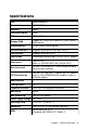
Specifications CPU 40MHz 80386SX Bus Interface PC/104 (ISA) bus Data Bus 16-bit Processing Ability 32-bit RAM memory 2MB or 4MB Shadow RAM Support for system and video BIOS up to 256KB in 32KB blocks Display Memory 512KB DRAM chip on board IDE HDD interface Supports up to two IDE (AT bus) HDDs FDD interface Supports up to two FDDs Parallel port Bi-directional parallel port (SPP/ECP/EPP modes) Serial ports Two RS-232 (both use 16C550 UART with 16-byte FIFO) Real time clock ALI M6117B i
4 PCM-3335 User's Manual
CHAPTER Installation 2 This chapter explains set up procedures for the PCM-3335 hardware, including instructions on setting jumpers and connecting peripherals, switches and indicators. Be sure to read all safety precautions before you begin the installation procedure.
Jumpers and connectors Connectors on the board link it to external devices such as hard disk drives, a keyboard, or floppy drives. In addition, the board has a number of jumpers that allow you to configure your system to suit your application. The table below lists the function of each of the board jumpers and connectors: Jumpers and connectors Number HARD CON. FLOPPY CON. FLAT PANEL CON. PRINTER PORT COM2 COM1 VGA CON. CN2 CN1 PS2 KB CN4, CN6 HD-LED RST SW.
Board Layout PC/104 Interface PS2 KB. PCM-3335 CN4 VGA CON. CN6 ALI DRAM DRAM M6117B UMC AMI Flash BIOS UM8663BF COM1 BAT. COM2 CLEAR CMOS FLAT PANEL CON. HD-LED HARD CON. RST SW. FLOPPY CON.
Setting jumpers You configure your card to match the needs of your application by setting jumpers. A jumper is the simplest kind of electric switch. It consists of two metal pins and a small metal clip (often protected by a plastic cover) that slides over the pins to connect them. To “close” a jumper you connect the pins with the clip. To “open” a jumper you remove the clip. Sometimes a jumper will have three pins, labeled 1, 2 and 3. In this case you would connect either pins 1 and 2 or 2 and 3.
Safety precautions Warning! Always completely disconnect the power cord from your chassis whenever you are working on it. Do not make connections while the power is on because sensitive electronic components can be damaged by the sudden rush of power. Only experienced electronics personnel should open the PC chassis. Caution! Always ground yourself to remove any static charge before touching the CPU card. Modern electronic devices are very sensitive to static electric charges.
IDE hard drive connections (HARD CON.) You can attach two Enhanced Integrated Device Electronics hard disk drives to the PCM-3335's internal controller. The card comes with a 40-pin flat cable. Connecting the hard drive Wire number 1 on the cable is red or blue, and the other wires are gray. 1. Connect one end of the cable to the IDE connector. Make sure that the red (or blue) wire corresponds to pin 1 on the connector, which is labeled on the board (on the right side). 2.
Pin assignments The following table lists the pin numbers and their respective signals: IDE Connector (HARD CON.) Pin 1 3 5 7 9 11 13 15 17 19 21 23 25 27 29 31 33 35 37 39 41 43 Signal Reset D7 D6 D5 D4 D3 D2 D1 D0 GND N.C, IOW IOR IORDY N.C. IRQ A1 A0 CS0 -ACT VCC GND Pin 2 4 6 8 10 12 14 16 18 20 22 24 26 28 30 32 34 36 38 40 42 44 Signal GND D8 D9 D10 D11 D12 D13 D14 D15 N.C. GND GND GND BALE GND -I/O CS16 N.C.
Floppy drive connections (FLOPPY CON.) You can attach up to two floppy disks to the PCM-3335's on-board controller. You can use any combination of 5¼" (360 KB and 1.2 MB) and/or 3½" (720 KB, 1.44 MB, and 2.88 MB) drives. The PCM-3335 CPU card comes with a 34-pin daisy-chain drive connector cable. On one end of the cable is a 34-pin flat-cable connector. There are two sets of floppy disk drive connectors, one in the middle, and one on the other end.
Parallel port (PRINTER PORT) Normally, the parallel port is used to connect the card to a printer. The PCM-3335 includes an on-board parallel port, accessed through PRINTER PORT, and a 26-pin flat-cable connector. The CPU card comes with an adapter cable, which lets you use a traditional DB-25 connector. The cable has a 26-pin connector on one end and a DB-25 connector on the other, mounted on a retaining bracket.
Power supply connections (CN4, CN6) Power supply connector In single board computer (non-passive backplane) applications, you will need to connect power directly to the PCM-3335 board using CN4 and CN6. This connector is fully compatible with the standard PC power supply connectors.
Display connections (VGA CON., FLAT PANEL CON.) The PCM-3335 CPU card's SVGA connector (VGA CON.) with PCI bus supports monochrome display as well as high resolution color displays. The card also features an LCD connector (FLAT PANEL CON.), which allows you to connect various flat panel displays. The following table lists their pin assignments: LCD connector (FLAT PANEL CON.
SVGA connector (VGA CON.
Keyboard connections (PS2 KB.) The PCM-3335 board provides one keyboard connector. A 5-pin connector (PS2 KB.) supports passive backplane applications. Keyboard connector (PS2 KB.) Pin 1 2 3 4 5 Function K.B. clock K.B. data N.C.
Serial ports (COM1, COM2) The PCM-3335 offers two serial ports (RS-232). These ports let you connect to serial devices (a mouse, printers, etc.), or a communication network. Reset switch (COM1, COM2) Pin 1 2 3 4 5 6 7 8 9 10 Signal DCD RxD TxD DTR GND DSR RTS CTS RI N/C Reset switch (RST SW.) You can connect an external switch to easily reset your computer. This switch restarts your computer as if you had turned off the power then turned it back on.
HDD LED (HD-LED) You can connect a LED to indicate that an IDE device is in use. The pin assignments for this jumper are as follows. HDD LED pin assignments (HD-LED) Pin 1 2 Function -R/W IDE Pull high Clear CMOS (CLEAR CMOS) You can connect an external switch to clear CMOS. This switch closes CLEAR CMOS and turns on the power, at which time the CMOS setup can be cleared.
20 PCM-3335 User's Manual
CHAPTER AMIBIOS Setup 3 This chapter describes how to set BIOS configuration data.
General information AMIBIOS Setup configures system information that is stored in CMOS RAM. Starting AMIBIOS setup As POST executes, the following appears; Hit if you want to run SETUP Press to run AMIBIOS setup. AMIBIOS main menu The AMIBIOS setup screen appears as follows: AMIBIOS SETUP — BIOS SETUP UTILITIES (C) 1995 American Megatrends, Inc.
Standard Setup The AMIBIOS Setup options described in this section are selected by choosing the Standard CMOS Setup from the AMIBIOS Setup main menu selection screen, as shown below. The Standard Setup screen appears: AMIBIOS SETUP — STANDARD CMOS SETUP (C) 1995 American Megatrends, Inc. All Rights Reserved Date (mm/dd/yyyy): Time (hh/mm/ss): Wed Aug 21, 1996 12: 19: 46 Floppy Drive A: Floppy Drive B: 1.
Master Disk, Slave Disk Select the appropriate values to configure the hard disk type you are using for the master and the slave. The settings have not been pre-installed. Available types are 1~46, User and Auto. Boot Sector Virus Protection Enabling this option allows the system to issue a warning when any program (or virus) issues a disk format command or attempts to write to the boot sector of the hard disk drive.
The following is a list of options offered by Advanced Setup.
Advanced Setup Options (continued) Onboard IDE Onboard FDC Onboard Serial Port 1 Onboard Serial Port 2 Onboard Parallel Port Parallel Port Mode ECP DMA Parallel Port IRQ 26 PCM-3335 User's Manual Disable Enable Disable Enable Disable 3F8 2F8 3E8 2E8 Disable 3F8 2F8 3E8 2E8 Disable 378 278 3BC SPP EPP ECP EPP & ECP DMA 3 DMA 1 IRQ 7 IRQ 5
Advanced Chipset Setup Select the Advanced Chipset Setup from the AMIBIOS Setup main menu to enter the Chipset Setup. The standard options of the Chipset Setup are shown in the following table. A detailed list of available options is also provided. AMIBIOS SETUP — ADVANCED CHIPSET SETUP (C) 1995 American Megatrends, Inc.
Chipset Setup Options Function At Bus Clock Slow Refresh Memory Remap RAS Precharge Time RAS Active Time Insert Wait CAS Precharge Time Insert Wait Memory Write Insert Wait Memory Miss Read Insert Wait ISA I/O High Speed ISA Memory High Speed ISA Write cycle end Insert Wait I/O Recovery I/O Recovery Period On-Chip I/O Recovery 16-bit ISA Insert Wait 28 PCM-3335 User's Manual Options 14.318/2 PCLK2/10 15us 6Ous 120us Disable Enable 1.5T 2.5T 3.
Change User Password 1) Select this option from the main menu 2) Enter the Password and Press 3) Retype the Password and Press If you forget the user's password, please contact your distributor for another password which you can use to enter the BIOS setup and change your own password. Auto Configuration with Optimal Settings You can load the optimal default settings for the AMIBIOS setup options by selecting it from the main menu.
30 PCM-3335 User's Manual
CHAPTER SVGA Setup 4 The PCM-3335 features an on-board flat panel/VGA interface. This chapter provides instructions for installing and operating the software drivers on the included display driver diskette.
Simultaneous display mode The 65545 VGA BIOS supports monochrome LCD, EL, color TFT and STN LCD flat panel displays. It also supports interlaced and non-interlaced analog monitors (VGA color and VGA monochrome) in high-resolution modes while maintaining complete IBM VGA compatibility. Digital monitors (i.e. MDA, CGA, and EGA) are NOT supported. Multiple frequency (multisync) monitors are supported as analog monitors. Both CRT and panel displays can be used simultaneously.
Software support The drivers support the following applications using the filenames and resolutions listed: Application Windows 3.1 Filename LINEAR4.DRV LINEAR8.DRV AutoCAD R12 LINEAR16.DRV LINEAR24.DRV RCTURBOC.EXP Resolution 640x480 800x600 1024x768 640x480 800x600 1024x768 640x480 640x480 640x480 800x600 1024x768 640x480 800x600 1024x768 640x480 640x480 640x480 Lotus 1-2-3 2.0 and Lotus Symphony 1.0,1.1 V132X25.DRV 132x25 (Text) V132X50.DRV 132x50 (Text) VESA 1.2 VESA.
Word 5.0 Word 5.5 WordPerfect 5.0 WordPerfect 5.1 VGA600.VID VGA768.VID VGA55600.VID VGA55768.VID CHIPS600.WPD CHIPS768.WPD VGA600.VRS VGA768.VRS 800x600 1024x768 800x600 1024x768 800x600 1024x768 800x600 1024x768 16 16 16 16 16 16 16 16 Driver installation Necessary prerequisites The instructions in this manual assume that you understand elementary concepts of MS-DOS and the IBM Personal Computer.
Windows setup These drivers are designed to work with Microsoft Windows 3.1. You may install these drivers through Windows or in DOS. Step 1: Install Windows as you normally would for a VGA display. Run Windows to make sure that it is working correctly. Step 2: Place the display driver diskette in drive A. In Windows Program Manager, choose File from the Options Menu. Then from the pull-down menu, choose Run . . . . At the command line prompt, type A:\WINSETUP.
DOS Setup Step 1: Install Windows as you normally would for a VGA display. Run Windows to make sure that it is working correctly. Then exit Windows. Step 2: Place the display driver diskette in drive A. Type A: to make this the default drive. Type SETUP to run the driver SETUP program. Press any key to get to the applications list. Using the arrow keys, select Windows Version 3.1 and press the key.
Panning Drivers Special panning drivers are provided to allow high-resolution modes to be displayed on a flat panel or CRT. These drivers will show a section of a larger screen and will automatically pan, or scroll, the screen horizontally and vertically when the mouse reaches the edge of the display. Linear Acceleration Drivers A special high-performance linear acceleration driver is provided for 256-color modes. This driver may require special hardware and may not be supported on all systems.
AutoCAD R12 These drivers are designed to work with Autodesk AutoCAD R12. They conform to the Autodesk Device Interface (ADI) for Rendering drivers and Display drivers. These display list drivers accelerate redraw, pan, and zoom functions. Driver installation Step 1: Place the display driver diskette in drive A. Type A: to make this the default drive. Type SETUP to run the SETUP program. Press any key to get to the applications list.
Basic Configuration Menu This menu allows you to modify: Number of AutoCAD Command Lines Font Size 6x8/8x8/8x14/8x16/12x20/12x24 Dual Screen Enable/Disable User Interface Configuration Double Click Interval Time BP Button BP Highlight Patt Line/Xor Rect/Both BP Refresh Enable/Disable BP Cache Enable/Disable Expert Configuration Menu This menu allows you to modify: Display List Enable/Disable Drawing Cache Enable/Disable Use Acad 31 bit space? Yes/No Internal Command Echo Enable/Disable B
Lotus 1-2-3 and Lotus Symphony These drivers are designed to work with Lotus 1-2-3 versions 2.0, 2.01 and 2.2, and with Lotus Symphony versions 1.0 and 1.1. Driver installation Step 1: Place the display driver diskette into drive A. Make A the default drive by typing A: . Run the SETUP program by typing SETUP . Press any key to display a list of supported applications. Use the arrow keys to select Lotus/ Symphony, and press . A list of supported screen resolutions will be displayed.
Step 6: At this point the Installation Menu will prompt you for the name of your new Lotus configuration file. The Lotus system will prompt you with the default value — 123.SET, but you may want to use a filename that indicates the resolution of its driver. For example, if you installed the 132 column by 25 line driver, you could name this driver 132X25.SET, or if you installed the 80 by 50 driver, you may want to call the file 80X50.SET. Step 7: The installation of your Lotus 1-2-3 driver is now complete.
VESA The Video Electronics Standards Association (VESA) has created a standard for a Super VGA BIOS Extension (VBE). This defines a standard software interface to allow application programs to set and control extended video modes, such as 800x600 graphics, on video adapters from different manufacturers. The VESA driver adds this Super VGA BIOS Extension to the VGA BIOS. Any application program which supports the VESA standard driver interface can be used with this driver.
Word These drivers are designed to work with Microsoft Word 5.0 and 5.5. Driver installation If you have already installed Word on your computer, go to Step 2 to install the new video driver. Step 1: Install Word as normal. Step 2: After you complete the Word installation, place the display driver diskette into drive A. Make A the default drive by typing A: . Run the SETUP program by typing SETUP . Press any key to display a list of supported applications.
WordPerfect These drivers are designed to work with WordPerfect 5.0 or 5.1. They support 132-column display in editing mode, and highresolution graphics display in PreView mode. Driver installation Step 1: Place the display driver diskette into drive A. Make A the default drive by typing A: . Run the SETUP program by typing SETUP . Press any key to display a list of supported applications. Use the arrow keys to select WordPerfect and press .
Configuring WordPerfect 5.0 for 132 columns Follow these instructions to configure WordPerfect 5.0 for 132 column text mode: Step 1: To use the SETCOL program to set 132 columns and 25 rows, type the following command: SETCOL 132, 25 Step 2: Start WordPerfect. The program will detect the number of rows and columns automatically. If for some reason WordPerfect is unable to adapt to 132 columns by 25 rows, start WordPerfect with the following command: WP /SS=25,132 Configuring WordPerfect 5.
46 PCM-3335 User's Manual
APPENDIX Installing PC/104 Modules A This appendix gives instructions for installing PC/104 modules.
Installing PC/104 modules The PCM-3335's PC/104 connectors give you the flexibility to attach PC/104 expansion modules. These modules perform the functions of traditional plug-in expansion cards, but save space and valuable slots.
Step4 Mount the PC/104 module onto the CPU card. Do this by pressing the module firmly but carefully onto the mounting connectors. Step5 Secure the PC/104 module onto the CPU card using the four mounting spacers and screws.
3.500 3.250 3.775 3.575 3.575 0.200 0.200 0 0.200 0 3.350 3.
APPENDIX LCD Display BIOS Configuration B This appendix gives instructions for configuring various LCD displays.
Configuring various LCD display Follow the instructions below to integrate an LCD VGA BIOS into the PCM-3335 system BIOS. 1. Combine the VGA BIOS with the system BIOS following the instructions at the DOS prompt. DEBUG -N -L -N -L -R CX 2000 :0 -R BX 0000 :2 -N 4000:0 CX ; DOS utility program ; Read STN.DAT in BIOS files for example BX -W -Q 4000:0 SBC-355.ROM 4000:0