Embedded Controller AEC-6831 AEC-6831 Fanless Embedded Controller Intel® Atom N270 1.6GHz CPU With Dual GbE Ethernet, 2 COMs, Audio, CompactFlash™ AEC-6831 Manual 1st Ed.
Embedded Controller AEC-6831 Copyright Notice This document is copyrighted, 2009. All rights are reserved. The original manufacturer reserves the right to make improvements to the products described in this manual at any time without notice. No part of this manual may be reproduced, copied, translated, or transmitted in any form or by any means without the prior written permission of the original manufacturer. Information provided in this manual is intended to be accurate and reliable.
Embedded Controller AEC-6831 Acknowledgments • Award is a trademark of Award Software International, Inc. • CompactFlash™ is a trademark of the Compact Flash Association. ® ® • Intel , Atom™ are trademarks of Intel Corporation. • Microsoft Windows is a registered trademark of Microsoft ® Corp. • ITE is a trademark of Integrated Technology Express, Inc. • IBM, PC/AT, PS/2, and VGA are trademarks of International Business Machines Corporation.
Embedded Controller AEC-6831 Packing List Before you begin operating your PC, please make sure that the following materials have been shipped: 1 AEC-6831 Embedded Controller 1 Phoenix Power Connector 2 Wallmount Brackets 1 Screw Package 1 Heat Spreading 1 CD-ROM for manual (in PDF format) and drivers If any of these items should be missing or damaged, please contact your distributor or sales representative immediately.
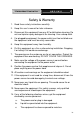
Embedded Controller AEC-6831 Safety & Warranty 1. Read these safety instructions carefully. 2. Keep this user's manual for later reference. 3. Disconnect this equipment from any AC outlet before cleaning. Do not use liquid or spray detergents for cleaning. Use a damp cloth. 4. For pluggable equipment, the power outlet must be installed near the equipment and must be easily accessible. 5. Keep this equipment away from humidity. 6. Put this equipment on a firm surface during installation.
Embedded Controller AEC-6831 d. The equipment does not work well, or you cannot get it to work according to the user’s manual. e. The equipment has been dropped and damaged. f. The equipment has obvious signs of breakage. 15. DO NOT LEAVE THIS EQUIPMENT IN AN ENVIRONMENT WHERE THE STORAGE TEMPERATURE IS BELOW -20°C (-4°F) OR ABOVE 60°C (140°F). IT MAY DAMAGE THE EQUIPMENT. FCC This device complies with Part 15 FCC Rules.
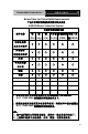
Embedded Controller AEC-6831 Below Table for China RoHS Requirements 产品中有毒有害物质或元素名称及含量 AAEON Boxer/ Industrial System 有毒有害物质或元素 部件名称 铅 汞 (Pb) (Hg) 印刷电路板 镉 六价铬 多溴联苯 多溴二苯 (Cd) (Cr(VI)) (PBB) 醚(PBDE) × ○ ○ ○ ○ ○ × ○ ○ ○ ○ ○ × ○ ○ ○ ○ ○ × ○ ○ ○ ○ ○ 硬盘 × ○ ○ ○ ○ ○ 电源 × ○ ○ ○ ○ ○ 及其电子组件 外部信号 连接器及线材 外壳 中央处理器 与内存 O:表示该有毒有害物质在该部件所有均质材料中的含量均在 SJ/T 11363-2006 标准规定的限量要求以下。 X:表示该有毒有害物质至少在该部件的某一均质材料中的含量超出 SJ/T 11363-2006 标准规定的限量要求。 备注: 一、此产品所标示之环保使用期限,系指在一般正常使用状况下。 二、上述部件物
Embedded Controller AEC-6831 Contents Chapter 1 General Information 1.1 Introduction................................................................ 1-2 1.2 Features .................................................................... 1-3 1.3 Specifications ............................................................ 1-4 Chapter 2 Hardware Installation 2.1 Dimension ................................................................. 2-2 2.2 Hard Disk Drive (HDD) Installation............................
Embedded Controller AEC-6831 Appendix B I/O Information B.1 I/O Address Map ....................................................B-2 B.2 1st MB Memory Address Map ................................B-3 B.3 IRQ Mapping Chart ................................................B-4 B.4 DMA Channel Assignments...................................
Embedded Controller AEC-6831 Chapter 1 General Information Chapter 1 General Information 1- 1
Embedded Controller AEC-6831 1.1 Introduction The AEC-6831 is an Embedded Control PC with Intel Atom Processor. The Anti-vibration and high temperature tolerances are the main design features of the AEC-6831. This allows the AEC-6831 to be installed in a rugged transportation environment despite high ambient vibration and temperature.
Embedded Controller AEC-6831 1.2 Features • Fanless Design with Intel® Atom (N270) 1.6 GHz processor • Mini PCI slots inside for expansion • DC 9~30V input with Phoenix connector and optional external AC power adapter • Front accessible USB port. • CFD / Optional 2.
Embedded Controller AEC-6831 1.3 Specifications System • CPU: Intel® Atom (N270) 1.6 GHz • Chipset Intel® 945GSE + ICH7M • Memory: 200-pin DDRII SODIMM x 1, Max. 2GB (DDRII 400/533) • Expansion: Mini PCI x 1 • VGA: VGA (DB-15) x 1 • Display Interface: DVI-D x 1 • Ethernet: Intel® 82574L, 10/100/1000Base-TX, RJ-45 x 2 • SSD: • Hard Disk Storage: Optional 2.5” Slim HDD kit • Serial Port: RS-232 x 1, RS-232/422/485 x 1 • Audio: Mic-in / Line-in / Line-out • USB: USB2.
Embedded Controller AEC-6831 HDD active LED x 1 Mechanical and Environmental • Construction: Aluminum Alloy chassis • Color: Dark Blue • Mounting: Wallmount (Default), DIN-Rail • Dimension: 8.35” (W) x 2.53” (H) x 4.21” (D) 212.15mm x 64.2mm x 107mm • Net Weight: 4.75lb (2.16kg) • Gross Weight: 8.36lb (3.
Embedded Controller AEC-6831 Front Side Power Rear Side Chapter 1 General Information 1-6 CFD
Embedded Controller AEC-6831 Chapter 2 Hardware Installation Chapter 2 Hardware Installation 2-1
Embedded Controller AEC-6831 2.
Embedded Controller AEC-6831 2.2 Hard Disk Drive (HDD) Installation Step 1: Open the bottom case of AEC-6831 by loosening the screws Step 2: Get the Hard Disk Drive ready.
Embedded Controller AEC-6831 Step 3: Stack the HDD and bracket. Fasten HDD and bracket with the screws.
Embedded Controller AEC-6831 SATA Power Step 5: Fasten the bracket of HDD Chapter 2 Hardware Installation 2 - 5
Embedded Controller AEC-6831 Step 6: Fasten the bottom case of ACE-6831 Chapter 2 Hardware Installation 2 - 6
Embedded Controller AEC-6831 2.
Embedded Controller AEC-6831 Step 3: Unfasten the four screws on the bottom case of AEC-6831 Step 4: Insert the SDRAM to the memory slot Chapter 2 Hardware Installation 2 - 8
Embedded Controller AEC-6831 Step 5: Press the SDRAM and make sure that it has been inserted properly Step 6: Adhere the heat-spreading sheet to the SDRAM Chapter 2 Hardware Installation 2 - 9
Embedded Controller AEC-6831 Step 7: Close the bottom case of AEC-6831 and fasten the four screws on the bottom case 2.4 Wallmount Installation Fasten the brackets by screws.
Embedded Controller AEC-6831 2.5 DIN Rail Installation Step 1: Fix the DIN Rail kit with the screws on the chassis as the illustration shown. Step 2: Press the DIN Rail on the DIN Rail kit to fix it.
Embedded Controller AEC-6831 2.6 COM Port 1 Connector Pin Signal Pin Signal 1 DCDA 2 RXA 3 TXA 4 DTRA 5 Ground 6 DSRA 7 RTSA 8 CTSA 9 RIA 10 N/C 2.7 COM Port 2 Connector RS-232 Mode Pin Signal Pin Signal 1 DCDB 2 RXB 3 TXB 4 DTRB 5 Ground 6 DSRB 7 RTSB 8 CTSB 9 RIB / +5 Volt. / +12 Volt. 10 N/C RS-422 Mode Pin Signal Pin Signal 1 TXD- 2 RXD+ 3 TXD+ 4 RXD- 5 Ground 6 N/C 7 N/C 8 N/C 9 N/C / +5 Volt. / +12 Volt.
Embedded Controller AEC-6831 7 N/C 8 N/C 9 N/C / +5 Volt. / +12 Volt.
Embedded Controller AEC-6831 Chapter 3 Award BIOS Setup Chapter 3 Award BIOS Setup 3-1
Embedded Controller AEC-6831 3.1 System Test and Initialization These routines test and initialize board hardware. If the routines encounter an error during the tests, you will either hear a few short beeps or see an error message on the screen. There are two kinds of errors: fatal and non-fatal. The system can usually continue the boot up sequence with non-fatal errors.
Embedded Controller AEC-6831 3.2 Award BIOS Setup Awards BIOS ROM has a built-in Setup program that allows users to modify the basic system configuration. This type of information is stored in battery-backed CMOS RAM so that it retains the Setup information when the power is turned off. Entering Setup Power on the computer and press immediately. This will allow you to enter Setup. Standard CMOS Features Use this menu for basic system configuration. (Date, time, IDE, etc.
Embedded Controller AEC-6831 PC Health Status This menu allows you to set the shutdown temperature for your system. Frequency/Voltage Control Use this menu to specify your settings for auto detect DIMM/PCI clock and spread spectrum. Load Fail-Safe Defaults Use this menu to load the BIOS default values for the minimal/stable performance for your system to operate. Load Optimized Defaults Use this menu to load the BIOS default values that are factory settings for optimal performance system operations.
Embedded Controller AEC-6831 Chapter 4 Driver Installation .
Embedded Controller AEC-6831 The AEC-6831 comes with an AutoRun CD-ROM that contains all drivers and utilities that can help you to install the driver automatically. Insert the driver CD, the driver CD-title will auto start and show the installation guide. If not, please follow the sequence below to install the drivers. Follow the sequence below to install the drivers: Step 1 – Install INF Driver Step 2 – Install VGA Driver Step 3 – Install LAN Driver Step 4 – Install Audio Driver USB 2.
Embedded Controller 4.1 AEC-6831 Installation: Insert the AEC-6831 CD-ROM into the CD-ROM drive. And install the drivers from Step 1 to Step 4 in order. Step 1 – Install INF Driver 1. Click on the Step 1 - INF Update Utility v8.2.0.1014 folder and double click on the Setup.exe 2. Follow the instructions that the window shows 3. The system will help you install the driver automatically Step 2 – Install VGA Driver 1.
Embedded Controller AEC-6831 Step 4 –Install Audio Driver 1. Click on the Step 4 - Realtek ALC655 Audio Driver v3.71 folder and select the OS folder your system is 2. Double click on setup.exe file located in each OS folder 3. Follow the instructions that the window shows 4.
Embedded Controller AEC-6831 Appendix A Programming the Watchdog Timer Appendix A Programming the Watchdog Timer A-1
Embedded Controller AEC-6831 A.1 Programming AEC-6831 utilizes ITE 8781 chipset as its watchdog timer controller. Below are the procedures to complete its configuration and the AAEON initial watchdog timer program is also attached based on which you can develop customized program to fit your application. Configuring Sequence Description After the hardware reset or power-on reset, the ITE 8781 enters the normal mode with all logical devices disabled except KBC.
Embedded Controller AEC-6831 There are three steps to complete the configuration setup: (1) Enter the MB PnP Mode; (2) Modify the data of configuration registers; (3) Exit the MB PnP Mode. Undesired result may occur if the MB PnP Mode is not exited normally. (1) Enter the MB PnP Mode To enter the MB PnP Mode, four special I/O write operations are to be performed during Wait for Key state.
Embedded Controller AEC-6831 WatchDog Timer Configuration Registers Configure Control (Index=02h) This register is write only. Its values are not sticky; that is to say, a hardware reset will automatically clear the bits, and does not require the software to clear them.
Embedded Controller AEC-6831 Watch Dog Timer 1, 2, 3 Configuration Register (Index=72h, 82h, 92h Default=001s0000b) Watch Dog Timer 1,2,3 Time-Out Value (LSB) Register (Index=73h,83h,93h, Default=38h) Watch Dog Timer 1,2,3 Time-Out Value (MSB) Register (Index=74h,84h,94h Default=00h) Appendix A Programming the Watchdog Timer A-5
Embedded Controller AEC-6831 A.2 ITE8781 Watchdog Timer Initial Program .MODEL SMALL .CODE Main: CALL Enter_Configuration_mode CALL Check_Chip mov cl, 7 call Set_Logic_Device ;time setting mov cl, 10 ; 10 Sec dec al Watch_Dog_Setting: ;Timer setting mov al, cl mov cl, 73h call Superio_Set_Reg ;Clear by keyboard or mouse interrupt mov al, 0f0h mov cl, 71h call Superio_Set_Reg ;unit is second.
Embedded Controller AEC-6831 call Superio_Set_Reg ; game port enable mov cl, 9 call Set_Logic_Device Initial_OK: CALL Exit_Configuration_mode MOV AH,4Ch INT 21h Enter_Configuration_Mode PROC NEAR MOV SI,WORD PTR CS:[Offset Cfg_Port] MOV DX,02Eh MOV CX,04h Init_1: MOV AL,BYTE PTR CS:[SI] OUT DX,AL INC SI LOOP Init_1 RET Enter_Configuration_Mode ENDP Exit_Configuration_Mode PROC NEAR MOV AX,0202h Appendix A Programming the Watchdog Timer A-7
Embedded Controller CALL Write_Configuration_Data RET Exit_Configuration_Mode ENDP Check_Chip PROC NEAR MOV AL,20h CALL Read_Configuration_Data CMP AL,87h JNE Not_Initial MOV AL,21h CALL Read_Configuration_Data CMP AL,81h JNE Not_Initial Need_Initial: STC RET Not_Initial: CLC RET Check_Chip ENDP Read_Configuration_Data PROC NEAR MOV DX,WORD PTR CS:[Cfg_Port+04h] Appendix A Programming the Watchdog Timer A-8 AEC-6831
Embedded Controller AEC-6831 OUT DX,AL MOV DX,WORD PTR CS:[Cfg_Port+06h] IN AL,DX RET Read_Configuration_Data ENDP Write_Configuration_Data PROC NEAR MOV DX,WORD PTR CS:[Cfg_Port+04h] OUT DX,AL XCHG AL,AH MOV DX,WORD PTR CS:[Cfg_Port+06h] OUT DX,AL RET Write_Configuration_Data ENDP Superio_Set_Reg proc near push ax MOV DX,WORD PTR CS:[Cfg_Port+04h] mov al,cl out dx,al pop ax inc dx out dx,al ret Superio_Set_Reg endp.
Embedded Controller Set_Logic_Device proc AEC-6831 near push ax push cx xchg al,cl mov cl,07h call Superio_Set_Reg pop cx pop ax ret Set_Logic_Device endp ;Select 02Eh->Index Port, 02Fh->Data Port Cfg_Port DB 087h,001h,055h,055h DW 02Eh,02Fh END Main Note: Interrupt level mapping 0Fh-Dh: not valid 0Ch: IRQ12 . .
Embedded Controller AEC-6831 Appendix B I/O Information Appendix B I/O Information B - 1
Embedded Controller B.
Embedded Controller AEC-6831 B.
Embedded Controller B.3 IRQ Mapping Chart B.