A d va n c e d S ys t e m Controller AIS-E1-H61A AIS-E1-H61A Advanced System Controller 3.5” HDD x 1, 2.5” HDD/SSD x 1 or 2.5” HDD/SSD x 2 Gigabit Ethernet x 2 COM x 6, USB2.0 x 8, CF-SATA x 1 Mini PCI-E x 1, PCI-E[x4] x 1 HD Audio Codec AIS-E1 Manual 1st Ed.
A d va n c e d S ys t e m Controller AIS-E1-H61A Copyright Notice T This document is copyrighted, 2013. All rights are reserved. The original manufacturer reserves the right to make improvements to the products described in this manual at any time without notice. No part of this manual may be reproduced, copied, translated, or transmitted in any form or by any means without the prior written permission of the original manufacturer.
A d va n c e d S ys t e m Controller AIS-E1-H61A Acknowledgments All other products’ name or trademarks are properties of their respective owners. AMI is a trademark of American Megatrends Inc. CompactFlash™ is a trademark of the Compact Flash Association. Intel® , Core and Celeron® are trademarks of Intel® Corporation. Microsoft Windows® is a registered trademark of Microsoft Corp. ITE is a trademark of Integrated Technology Express, Inc.
A d va n c e d S ys t e m Controller AIS-E1-H61A Packing List Before you begin operating your PC, please make sure that the following materials are enclosed: 1 COM Port Cable 1 CPU Cooler 1 84W Adapter 1 SATA Cable 1 SATA Power Cable 4 Rubber Foot 1 AIS-E1-H61A 1 DVD-ROM for manual (in PDF format) and drivers If any of these items should be missing or damaged, please contact your distributor or sales representative immediately.
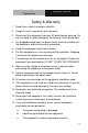
A d va n c e d S ys t e m Controller AIS-E1-H61A Safety & Warranty 1. Read these safety instructions carefully. 2. Keep this user's manual for later reference. 3. Disconnect this equipment from any AC outlet before cleaning. Do not use liquid or spray detergents for cleaning. Use a damp cloth. 4. For pluggable equipment, the power outlet must be installed near the equipment and must be easily accessible. 5. Keep this equipment away from humidity. 6.
A d va n c e d S ys t e m Controller AIS-E1-H61A d. The equipment does not work well, or you cannot get it to work according to the user’s manual. e. The equipment has been dropped and damaged. f. The equipment has obvious signs of breakage. 15. DO NOT LEAVE THIS EQUIPMENT IN AN ENVIRONMENT WHERE THE STORAGE TEMPERATURE IS BELOW -20°C (-4°F) OR ABOVE 65°C (149°F). IT MAY DAMAGE THE EQUIPMENT. FCC This device complies with Part 15 FCC Rules.
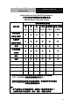
A d va n c e d S ys t e m Controller AIS-E1-H61A Below Table for China RoHS Requirements 产品中有毒有害物质或元素名称及含量 AAEON Boxer/ Industrial System 有毒有害物质或元素 部件名称 铅 汞 镉 (Pb) (Hg) (Cd) (Cr(VI)) (PBB) (PBDE) × ○ ○ ○ ○ ○ × ○ ○ ○ ○ ○ × ○ ○ ○ ○ ○ × ○ ○ ○ ○ ○ 硬盘 × ○ ○ ○ ○ ○ 电源 × ○ ○ ○ ○ ○ 印刷电路板 六价铬 多溴联苯 多溴二苯醚 及其电子组件 外部信号 连接器及线材 外壳 中央处理器 与内存 O:表示该有毒有害物质在该部件所有均质材料中的含量均在 SJ/T 11363-2006 标准规定的限量要求以下。 X:表示该有毒有害物质至少在该部件的某一均质材料中的含量超出 SJ/T 11363-2006 标准规定的限量要求。 备注: 一、此产品所标示之环保使用
A d va n c e d S ys t e m Controller AIS-E1-H61A Contents T Chapter 1 General Information 1.1 Introduction ................................................................ 1-2 1.2 Features .................................................................... 1-3 1.3 Specifications ............................................................ 1-4 Chapter 2 Hardware Installation 2.1 Location of Connectors (Main Board) ....................... 2-2 2.2 Mechanical Drawing of AIS-E1-H61A .....................
A d va n c e d S ys t e m Controller AIS-E1-H61A 2.16 Debug Connector (DEBUG) .................................... 2-11 2.17 Front Panel Connector (F_PANEL) ......................... 2-11 2.18 Inverter Connector (INV) ......................................... 2-11 2.19 LVDS Panel Signal Connector (LVDS) ................... 2-12 2.20 SATA Power Connector (PWR1) ............................ 2-13 2.21 FAN Connector (S_FAN1/S_FAN2) ........................ 2-13 2.22 BIOS Programmable Connector (SPI) .........
A d va n c e d S ys t e m Controller Appendix C AIS-E1-H61A AHCI Setting C.1 Setting AHCI ......................................................... C-2 Appendix D Electrical Specifications for I/O Ports D.1 DIO Programming ................................................. D-2 D.2 Digital I/O Register ................................................ D-3 D.3 Digital I/O Sample Program ..................................
A d va n c e d S ys t e m Controller AIS-E1-H61A Chapter 1 General Information Chapter 1 General Information 1- 1
A d va n c e d S ys t e m Controller AIS-E1-H61A 1.1 Introduction AIS-E1-H61A adopts the 2 nd ® TM generation Intel Core i7/ i5/ ® ® Celeron processor up to 35W. The chipset is equipped with Intel H61. Moreover, the system memory features two DDR3 1066/1333 MHz SODIMM up to 16 GB. It deploys two LAN ports that consist of 10/100/1000Base-TX Ethernet RJ-45 ports. AIS-E1-H61A condensed appearance features desktop and wallmount form factor that fits nicely into a space-limited environment.
A d va n c e d S ys t e m Controller AIS-E1-H61A 1.2 Features Mini-ITX based chassis with scalable expansion slots ® Socket LGA 1155 2nd generation for Intel Core™ i7 ® / i5 / Celeron processors up to 35W 2 x 204-pin Dual-channel DDR3 1066/1333 MHz SODIMM up to 16GB ® Intel Integrated Graphics Engine supports dual view by VGA, DVI, HDMI Realtek RTL 8111E Gigabit Ethernet x 2 Up to 2.5” HDD/SSD x 2 or up to 2.5” HDD/SSD x 1 and 3.5” HDD/SSD x 1, support RAID 0,1,5,10 USB 2.
A d va n c e d S ys t e m Controller AIS-E1-H61A 1.3 Specifications CPU Socket LGA 1155 2nd Generation ® Intel Core™ i7 / i5 / Celeron ® processors up to 35W ® Chipset Intel H61 System Memory 204-pin Dual Channel DDR3 1066/1333 MHz SODIMM x2, up to 16GB Display Interface Storage Device VGA DB-15 x 1 DVI DVI-D x 1 Others HDMI x 1 SSD CF-SATA x 1 HDD 2.5” SATA HDD bay x 2 (optional 3.5” HDD x 1 + 2.
A d va n c e d S ys t e m Controller AIS-E1-H61A 5/12V, optional RS-232 x 5 Expansion Audio Mic-in, Line-in, Line-out KB/MS KB/MS x 1 Others Power input x 1 Mini Card - Others PCI-Express [x4] x 1, Mini-PCIe, CF-SATA x 1, Antenna hole x 2 Indicator Front Power Requirement PWR, HDD 100~240V AC to DC 12V power adapter System Cooling CPU cooler x 1 System Cooler x 1 Mounting Wallmount Operating Temperature 32°F ~ 113°F (0°C ~ 45°C) Storage Temperature -4°F ~ 140°F (-20°C
A d va n c e d S ys t e m Controller AIS-E1-H61A ® OS Support ® Windows XP Pro, Windows 7, ® Windows 8, Linux Kernal 2.6.
A d va n c e d S ys t e m Controller AIS-E1-H61A Chapter 2 Hardware Installation Chapter 2 Hardware Installation 2-1
A d va n c e d S ys t e m Controller AIS-E1-H61A 2.
A d va n c e d S ys t e m Controller AIS-E1-H61A Solder Side Chapter 2 Hardware Installation 2-3
A d va n c e d S ys t e m Controller AIS-E1-H61A 2.
A d va n c e d S ys t e m Controller AIS-E1-H61A 2.3 List of Jumpers The board has a number of jumpers that allow you to configure your system to suit your application. The table below shows the function of each of the board's jumpers: Label Function CLRTC1 Clear CMOS J1 LVDS Panel Voltage Selection J2 Inverter Voltage Selection J3 Mode Selection for Back Light Control of Inverter J4 AT/ATX mode Selection J5 COM1 Ring/+5V/+12V Selection 2.
A d va n c e d S ys t e m Controller AIS-E1-H61A CON14 COM1 & DVI-D Connector CON17 LAN1 and USB1/2 Connector CON18 LAN2 and USB3/4 Connector CON19 PS/2 KB&MS and USB5/6 Connector CON2 D-Sub15_VGA Connector with HDMI Connector CON3 mini PCI-E Slot CON4 Compact Flash Slot DEBUG Debug Connector DIMM_A1 DIMM1 Slot DIMM_B1 DIMM2 Slot DIO Digital I/O Connector F_PANEL Front Panel Connector INV Inverter Connector LGA1 CPU Socket - LGA-1155P LVDS LVDS Panel Signal Connector PCIEX4
A d va n c e d S ys t e m Controller AIS-E1-H61A 2.5 Setting Jumpers You configure your card to match the needs of your application by setting jumpers. A jumper is the simplest kind of electric switch. It consists of two metal pins and a small metal clip (often protected by a plastic cover) that slides over the pins to connect them. To “close” a jumper you connect the pins with the clip. To “open” a jumper you remove the clip. Sometimes a jumper will have three pins, labeled 1, 2 and 3.
A d va n c e d S ys t e m Controller AIS-E1-H61A 2.6 Clear CMOS (CLRTC1) CLRTC1 Function 1-2 Protected (Default) 2-3 Clear 2.7 LVDS Panel Voltage Selection (J1) J1 Function 1-2 +5V 2-3 +3.3V (Default) 2.8 Inverter Voltage Selection (J2) J2 Function 1-2 +12V 2-3 +5V (Default) 2.9 Mode Selection for Back Light Control of Inverter (J3) J3 Function 1-2 DC Voltage Control (Default) 2-3 PWM Control 2.
A d va n c e d S ys t e m Controller AIS-E1-H61A 2.11 COM1 Ring/+5V/+12V Selection (J5) J5 Function 1-2 +12V 3-4 +5V 5-6 Ring (Default) 2.12 Internal COM Serial Port Connector (COM2 ~ COM6) Pin Signal Pin Signal 1 DCD 2 RXD 3 TXD 4 DTR 5 GND 6 DSR 7 RTS 8 CTS 9 RI 10 (NC) 2.13 PS/2 Keyboard/Mouse Connector with Dock USB 2.
A d va n c e d S ys t e m Controller AIS-E1-H61A 2.14 1000Base-T Ethernet Connector with Dock USB 2.
A d va n c e d S ys t e m Controller AIS-E1-H61A 2.16 Debug Connector (DEBUG) Pin Signal 1 LPC_AD0 2 LPC_AD1 3 LPC_AD2 4 LPC_AD3 5 +3.3V 6 LPC_FRAME# 7 PLTRST# 8 GND 9 CLK_33M_LPC 10 LPC_DRQ#0 11 LPC_DRQ#1 12 SERIRQ# 2.17 Front Panel Connector (F_PANEL) Pin Signal Pin Signal 1 HDLED+ 2 PLED+ 3 HDLED- 4 PLED- 5 GND 6 PANSWH# 7 HWRST# 8 GND 9 (NC) 10 (kill pin) 2.
A d va n c e d S ys t e m Controller AIS-E1-H61A 3 Back Light Control 5 GND 7 GND 9 Back Light Enable 2.
A d va n c e d S ys t e m Controller KB&MS USB 1 AIS-E1-H61A SATA 29 2 30 COM DVI-D 2.20 SATA Power Connector (PWR1) Pin Signal 1 +5V 2 GND 3 GND 4 +12V 2.21 FAN Connector (S_FAN1/S_FAN2) Pin Signal 1 PWM 2 SENSE 3 VCC 4 GND 2.22 BIOS Programmable Connector (SPI) 4B Pin 25B Signal Pin Signal 1 +V3.
A d va n c e d S ys t e m Controller AIS-E1-H61A 5 SPI_MISO 6 SPI_MOSI 7 (NC) 8 (NC) 2.23 Internal USB 2.0 Connector (USB1) Pin Signal Pin Signal 1 +5V 2 GND 3 USB2_DN1 4 GND 5 USB2_DP1 6 USB2_DP2 7 GND 8 USB2_DN2 9 GND 10 +5V 2.
A d va n c e d S ys t e m Controller AIS-E1-H61A Step 2: Open the upper cover of the AIS-E1-H61A Step 3: Get the HDD Bracket and fasten the four screws with the HDD Chapter 2 Hardware Installation 2-15
A d va n c e d S ys t e m Controller AIS-E1-H61A Step 4: Put the HDD and bracket back to the chassis by sliding the HDD bracket and lock to the position.
A d va n c e d S ys t e m Controller AIS-E1-H61A 2.25 Installing Three 2.5” Hard Disk Drives If you have three HDD to install, please refer to the installation below.
A d va n c e d S ys t e m Controller AIS-E1-H61A Step 3: Put the blue rubber damper to the 3-layer HDD bracket and move the damper to the smaller fillister (you have to put 12 blue rubber dampers if you have three HDD to install) Chapter 2 Hardware Installation 2-18
A d va n c e d S ys t e m Controller AIS-E1-H61A Step 4: Get the four screws ready and pierce to the dampers and lock the HDD (12 screws for three HDD installations) Chapter 2 Hardware Installation 2-19
A d va n c e d S ys t e m Controller AIS-E1-H61A Step 5: Make sure that the fillisters of the 3-layer HDD bracket has been latched to I-shape nails (blue circles) fillister fillister 3-layer HDD bracket Chapter 2 Hardware Installation 2-20
A d va n c e d S ys t e m Controller AIS-E1-H61A Step 6: Fasten the screw to lock the HDD bracket with the Chassis and you’ve done installing the three HDD Chapter 2 Hardware Installation 2-21
A d va n c e d S ys t e m Controller AIS-E1-H61A Chapter 3 AMI BIOS Setup Chapter 3 AMI BIOS Setup 3-1
A d va n c e d S ys t e m Controller 3.1 AIS-E1-H61A System Test and Initialization These routines test and initialize board hardware. If the routines encounter an error during the tests, you will either hear a few short beeps or see an error message on the screen. There are two kinds of errors: fatal and non-fatal. The system can usually continue the boot up sequence with non-fatal errors.
A d va n c e d S ys t e m Controller 3.2 AIS-E1-H61A AMI BIOS Setup AMI BIOS ROM has a built-in Setup program that allows users to modify the basic system configuration. This type of information is stored in battery-backed CMOS RAM so that it retains the Setup information when the power is turned off. Entering Setup Power on the computer and press or immediately. This will allow you to enter Setup. Main Set the date, use tab to switch between date elements.
A d va n c e d S ys t e m Controller Setup Menu Setup submenu: Main Chapter 3 AMI BIOS Setup 3-4 AIS-E1-H61A
A d va n c e d S ys t e m Controller AIS-E1-H61A Setup submenu: Advanced Chapter 3 AMI BIOS Setup 3-5
A d va n c e d S ys t e m Controller AIS-E1-H61A ACPI Settings Options summary : Suspend mode S1 (CPU Stop Clock) S3 (Suspend to RAM) Optimal Default, Failsafe Default Select the ACPI state used for System Suspend Chapter 3 AMI BIOS Setup 3-6
A d va n c e d S ys t e m Controller AIS-E1-H61A Trusted Computing Options summary: Security Device Disabled Optimal Default, Failsafe Support Default Enabled En/Disable TPM support. TPM State Disabled Optimal Default, Failsafe Default Enabled En/Disable TPM State.
A d va n c e d S ys t e m Controller Pending None Operation AIS-E1-H61A Optimal Default, Failsafe Default Enable Take Ownership Disable Take Ownership TPM Clear Select one-time TPM operation. Item value returns to „None‟ after next POST.
A d va n c e d S ys t e m Controller AIS-E1-H61A S5 RTC Wake Settings Options summary : Wake system with Disabled Fixed Time Optimal Default, Failsafe Default Enabled En/Disabled system wake on alarm event. When enabled, System will wake on the hr::min::sec specified.
A d va n c e d S ys t e m Controller AIS-E1-H61A En/Disabled system wake on alarm event. When enabled, System will wake on the current time + Increase minute(s).
A d va n c e d S ys t e m Controller AIS-E1-H61A CPU Configuration Options summary : Hyper-Threading Disabled Enabled Optimal Default, Failsafe Default En/Disable CPU Hyper-Threading function Intel Disabled Virtualization Enabled Optimal Default, Failsafe Default Technology En/Disable Intel VT-x function Chapter 3 AMI BIOS Setup 3-11
A d va n c e d S ys t e m Controller SATA Configuration Chapter 3 AMI BIOS Setup 3-12 AIS-E1-H61A
A d va n c e d S ys t e m Controller AIS-E1-H61A SATA Configuration (AHCI) Options summary : SATA#1 IDE Disabled Configuration Enabled Default Compatible: Configure SATA controller #1 as a legacy compatible controller. Enhanced: Configure SATA controller #1 as a Intel enhanced controller.
A d va n c e d S ys t e m Controller Hot Plug Disabled AIS-E1-H61A Optimal Default, Failsafe Default Enabled En/Disable Hot Plug feature.
A d va n c e d S ys t e m Controller AIS-E1-H61A USB Configuration Options summary: Legacy USB Support Enabled Optimal Default, Failsafe Default Disabled Auto Enables BIOS Support for Legacy USB Support. When enabled, USB can be functional in legacy environment like DOS.
A d va n c e d S ys t e m Controller AIS-E1-H61A Floppy Forced FDD Hard Disk CDROM If Auto. USB devices less than 530MB will be emulated as Floppy and remaining as Floppy and remaining as hard drive. Forced FDD option can be used to force a HDD formatted drive to boot as FDD(Ex.
A d va n c e d S ys t e m Controller AIS-E1-H61A Serial Port Configuration Options summary : F81866 ERP Function Disabled Default Enabled Enable or Disable ERP function. Serial Port Disabled Enabled Default Allows BIOS to En/Disable correspond serial port.
A d va n c e d S ys t e m Controller AIS-E1-H61A RS422 RS485 Select working model. Change Settings Auto Default (Serial Port 1) IO=3F8h; IRQ=4; IO=3F8h; IRQ=3,4; IO=2F8h; IRQ=3,4; IO=3E8h; IRQ=10,11; IO=2E8h; IRQ=10,11 Allows BIOS to Select Serial Port resource.
A d va n c e d S ys t e m Controller AIS-E1-H61A IO=2E8h; IRQ=10,11 Allows BIOS to Select Serial Port resource. Change Settings Auto Default (Serial Port 3) IO=3E8h; IRQ=10,11; IO=2E8h; IRQ=10,11; IO=2D0h; IRQ=10,11; IO=2D8h; IRQ=10,11 Allows BIOS to Select Serial Port resource.
A d va n c e d S ys t e m Controller AIS-E1-H61A Allows BIOS to Select Serial Port resource. Change Settings Auto Default (Serial Port 5) IO=2D0h; IRQ=10,11; IO=3E8h; IRQ=10,11; IO=2E8h; IRQ=10,11; IO=2D8h; IRQ=10,11 Allows BIOS to Select Serial Port resource.
A d va n c e d S ys t e m Controller AIS-E1-H61A On-Module H/W Monitor Chapter 3 AMI BIOS Setup 3-21
A d va n c e d S ys t e m Controller Smart Fan Mode Configuration Chapter 3 AMI BIOS Setup 3-22 AIS-E1-H61A
A d va n c e d S ys t e m Controller AIS-E1-H61A Options summary : SYS/CPU Smart Fan Auto by RPM Default Control Auto by Duty-Cycle Manual by RPM Manual by Duty-Cycle Chapter 3 AMI BIOS Setup 3-23
A d va n c e d S ys t e m Controller AIS-E1-H61A Select CPU Smart FAN mode Auto by RPM: Automatically controlling the fan to maintain target Fan Speed. Auto by Duty-Cycle: Automatically controlling the fan to maintain target temperature. Manual by RPM: Manually controlling the fan with a given Fan Speed. Manual by Duty-Cycle: Manually controlling the fan with a given control PWM. Target Temp. Sensor CPU Temperature PCH Temperature Select target temperature source.
A d va n c e d S ys t e m Controller AIS-E1-H61A PCH-IO Configuration Chapter 3 AMI BIOS Setup 3-25
A d va n c e d S ys t e m Controller AIS-E1-H61A Options summary : Azalia Disabled Enabled Optimal Default, Failsafe Default Enabling/Disabling HD Audio controller. Azalia internal HDMI Codec Disabled Optimal Default, Failsafe Default Enabled Enabling/Disabling internal HDMI codec.
A d va n c e d S ys t e m Controller AIS-E1-H61A Select power supply mode. Restore on AC Power Loss Power Off Power On Last State Default Select the action system to take when restoring from power loss. JMB 368 ATA Controller Disabled Enabled Default En/Disable JMB 368 ATA Controller. Mini PCI-E Gen Speed Gen1 Optimal Default, Failsafe Default Gen2 Select PCI Express Gen speed. Resume on Ring Disabled Default Enabled En/Disabled resuming from RI# signal.
A d va n c e d S ys t e m Controller AIS-E1-H61A System Agent(SA) Configuration Options summary : VT-d Disabled Enabled Default En/Disable chipset Virtualization Technology function. PCIE x 4 Gen Speed Gen1 Gen2 Select PCI Express Gen speed.
A d va n c e d S ys t e m Controller AIS-E1-H61A Graphics Configuration Options summary : Primary Display Auto Default IGFX PEG Select which of IGFX/PEG Graphics device should be Primary Display. Internal Graphics Auto Default Disable Enable Keep IGD enabled based on the setup options.
A d va n c e d S ys t e m Controller 2MB AIS-E1-H61A Default Select the GTT Size. Aperture Size 128MB 256MB Default 512MB Select the Aperture Size.
A d va n c e d S ys t e m Controller AIS-E1-H61A Select DVMT 5.0 Pre-Allocated(Fixed) Graphics Memory size used by the Internal Graphics Device. Primary IGFX Boot Display AUTO Default CRT HDMI LVDS DVI Select the Video Device which will be activated during POST. For dual-display, select “Auto”. Note: The platform only supports single display in legacy environment (DOS).
A d va n c e d S ys t e m Controller AIS-E1-H61A Setup submenu: Boot Options summary : Bootup NumLock State On Default Off Select the keyboard NumLock state. Quiet Boot Disabled Default Enabled En/Disable showing boot logo. Launch RTL8111E PXE Disabled OpROM Enabled Enable or Disable Legacy Boot Option for RTL811E.
A d va n c e d S ys t e m Controller GateA20 Active AIS-E1-H61A Upon Request Default Always UPON REQUEST – GA20 can be disabled using BIOS services. ALWAYS – do not allow disabling GA20; this option is useful when any RT code is executed above 1MB. Option ROM Messages Force BIOS Default Keep Current Set display mode for Option ROM.
A d va n c e d S ys t e m Controller AIS-E1-H61A Setup submenu: Security Change User/Supervisor Password You can install a Supervisor password, and if you install a supervisor password, you can then install a user password. A user password does not provide access to many of the features in the Setup utility. If you highlight these items and press Enter, a dialog box appears which lets you enter a password. letters or numbers. password.
A d va n c e d S ys t e m Controller AIS-E1-H61A Setup utility. Removing the Password Highlight this item and type in the current password. At the next dialog box press Enter to disable password protection.
A d va n c e d S ys t e m Controller Setup submenu: Exit Chapter 3 AMI BIOS Setup 3-36 AIS-E1-H61A
A d va n c e d S ys t e m Controller AIS-E1-H61A Chapter 4 Driver Installation 0B .
A d va n c e d S ys t e m Controller AIS-E1-H61A The AIS-E1-H61A comes with an AutoRun DVD-ROM that contains all drivers and utilities that can help you to install the driver automatically. Insert the driver DVD, the driver DVD-title will auto start and show the installation guide. If not, please follow the sequence below to install the drivers.
A d va n c e d S ys t e m Controller 4.1 AIS-E1-H61A Installation: Insert the AIS-E1-H61A DVD-ROM into the DVD-ROM drive. And install the drivers from Step 1 to Step 8 in order. Step 1 – Install Chipset Driver 1. Click on the Step 1 - INF folder and double click on the Setup.exe file 2. Follow the instructions that the window shows 3. The system will help you install the driver automatically Step 2 – Install VGA Driver 1.
A d va n c e d S ys t e m Controller AIS-E1-H61A 3. Follow the instructions that the window shows 4. The system will help you install the driver automatically Step 4 –Install Audio Driver 1. Click on the Step 4 - AUDIO folder and select the OS folder your system is 2. Double click on the Setup.exe located in each OS folder 3. Follow the instructions that the window shows 4. The system will help you install the driver automatically Step 5 – Install TPM Driver 1.
A d va n c e d S ys t e m Controller AIS-E1-H61A automatically Step 7 – Install AHCI Driver Please refer to the Appendix C AHCI Setting Step 8 –Install Serial Port Driver (Optional) ® For Windows XP 32-bit 1. Click on the Step 8 - Serial Port Driver (Optional) folder and select the folder of WINXP_32 2. Double click on the patch.bat 3. Follow the instructions that the window shows 4.
A d va n c e d S ys t e m Controller AIS-E1-H61A ® For Windows 7 32-bit/ 64-bit 1. Create a password for Administrator account. 2.
A d va n c e d S ys t e m Controller AIS-E1-H61A 3. Reboot and Administrator login. 4. To run patch.bat with [Run as administrator].
A d va n c e d S ys t e m Controller AIS-E1-H61A You also can install the serial port driver for Windows 7 by the Installation Procedure 2 below: -Win7 32-bit Copy the Driver CD\Serial Port Driver (Optional) \WIN7_32\ win7_X86 \serial.sys to C:\WINDOWS\system32\drivers\ -Win7 64-bit Copy the Driver CD\Serial Port Driver (Optional) \WIN7_64 \win7_amd64\serial.
A d va n c e d S ys t e m Controller AIS-E1-H61A Chapter 4 Driver Installation 4 -9
A d va n c e d S ys t e m Controller AIS-E1-H61A Appendix A Programming the Watchdog Timer Appendix A Programming the Watchdog Timer A-1
A d va n c e d S ys t e m Controller AIS-E1-H61A A.1 Watchdog Timer Initial Program Table 1 : SuperIO relative register table Default Value Index 0x2E(Note1) Data 0x2F(Note2) Note SIO MB PnP Mode Index Register 0x2E or 0x4E SIO MB PnP Mode Data Register 0x2F or 0x4F Table 2 : Watchdog relative register table LDN Register BitNum Value Note Time of watchdog timer Timer Counter 0x07(Note3) 0xF6(Note4) (Note24) (0~255) This register is byte access Select time unit.
A d va n c e d S ys t e m Controller AIS-E1-H61A #define void IOWriteByte(byte IOPort, byte Value); #define byte IOReadByte(byte IOPort); // Watch Dog relative definition (Please reference to Table 2) #define byte TimerLDN //This parameter is represented from Note3 #define byte TimerReg //This parameter is represented from Note4 #define byte TimerVal // This parameter is represented from Note24 #define byte UnitLDN //This parameter is represented from Note5 #define byte UnitReg //This parameter is represe
A d va n c e d S ys t e m Controller AIS-E1-H61A ************************************************************************************ VOID Main(){ // Procedure : AaeonWDTConfig // (byte)Timer : Time of WDT timer.(0x00~0xFF) // (boolean)Unit : Select time unit(0: second, 1: minute). AaeonWDTConfig(); // Procedure : AaeonWDTEnable // This procudure will enable the WDT counting.
A d va n c e d S ys t e m Controller AIS-E1-H61A ************************************************************************************ // Procedure : AaeonWDTEnable VOID AaeonWDTEnable (){ WDTEnableDisable(EnableLDN, EnableReg, EnableBit, 1); } // Procedure : AaeonWDTConfig VOID AaeonWDTConfig (){ // Disable WDT counting WDTEnableDisable(EnableLDN, EnableReg, EnableBit, 0); // Clear Watchdog Timeout Status WDTClearTimeoutStatus(); // WDT relative parameter setting WDTParameterSetting(); } VOID WDTEnableDis
A d va n c e d S ys t e m Controller AIS-E1-H61A ************************************************************************************ VOID SIOEnterMBPnPMode(){ IOWriteByte(SIOIndex, 0x87); IOWriteByte(SIOIndex, 0x87); } VOID SIOExitMBPnPMode(){ IOWriteByte(SIOIndex, 0xAA); } VOID SIOSelectLDN(byte LDN){ IOWriteByte(SIOIndex, 0x07); // SIO LDN Register Offset = 0x07 IOWriteByte(SIOData, LDN); } VOID SIOBitSet(byte LDN, byte Register, byte BitNum, byte Value){ Byte TmpValue; SIOEnterMBPnPMode(); SIOSelectLD
A d va n c e d S ys t e m Controller AIS-E1-H61A Appendix B I/O Information Appendix B I/O Information B-1
A d va n c e d S ys t e m Controller B.
A d va n c e d S ys t e m Controller AIS-E1-H61A Appendix B I/O Information B-3
A d va n c e d S ys t e m Controller st B.
A d va n c e d S ys t e m Controller AIS-E1-H61A B.
A d va n c e d S ys t e m Controller Appendix B I/O Information B-6 AIS-E1-H61A
A d va n c e d S ys t e m Controller AIS-E1-H61A B.
A d va n c e d S ys t e m Controller AIS-E1-H61A Appendix C AHCI Setting Appendix C AHCI Setting C-1
A d va n c e d S ys t e m Controller AIS-E1-H61A C.
A d va n c e d S ys t e m Controller AIS-E1-H61A Step 4: The setting procedures “In BIOS Setup Menu” B: Boot -> Boot Option #1 -> DVD-ROM Type Step 5: The setting procedures “In BIOS Setup Menu” C: Save & Exit -> Save Changes and Exit Appendix C AHCI Setting C-3
A d va n c e d S ys t e m Controller Step 6: Setup OS Step 7: Press “F6” Appendix C AHCI Setting C-4 AIS-E1-H61A
A d va n c e d S ys t e m Controller AIS-E1-H61A Step 8: Choose “S” Step 9: Choose “Intel(R) 5 Series 6 Port SATA AHCI Controller” Appendix C AHCI Setting C-5
A d va n c e d S ys t e m Controller AIS-E1-H61A Step 10: It will show the model number you select and then press “ENTER” Step 11: Setup is loading files Appendix C AHCI Setting C-6
A d va n c e d S ys t e m Controller AIS-E1-H61A Appendix D Electrical Specifications For I/O Ports Appendix D Electrical Specifications for I/O Ports D-1
A d va n c e d S ys t e m Controller AIS-E1-H61A D.1 DIO Programming AIS-E1-H61A utilizes FINTEK 81866 chipset as its Digital I/O controller. Below are the procedures to complete its configuration and the AAEON initial watchdog timer program is also attached based on which you can develop customized program to fit your application. There are three steps to complete the configuration setup: (1) Enter the MB PnP Mode; (2) Modify the data of configuration registers; (3) Exit the MB PnP Mode.
A d va n c e d S ys t e m Controller AIS-E1-H61A D.
A d va n c e d S ys t e m Controller AIS-E1-H61A D.
A d va n c e d S ys t e m Controller AIS-E1-H61A ************************************************************************************ // Digital Output control relative definition (Please reference to Table 3) #define byte DOutput1LDN // This parameter is represented from Note27 #define byte DOutput1Reg // This parameter is represented from Note28 #define byte DOutput1Bit // This parameter is represented from Note29 #define byte DOutput1Val // This parameter is represented from Note30 #define byte DOutput
A d va n c e d S ys t e m Controller AIS-E1-H61A ************************************************************************************ VOID Main(){ Boolean PinStatus ; // Procedure : AaeonReadPinStatus // Input : // Example, Read Digital I/O Pin 3 status // Output : // InputStatus : // 0: Digital I/O Pin level is low // 1: Digital I/O Pin level is High PinStatus = AaeonReadPinStatus(DInput3LDN, DInput3Reg, DInput3Bit); // Procedure : AaeonSetOutputLevel // Input : // Example, Set Digital I/O Pin 6 level Aa
A d va n c e d S ys t e m Controller AIS-E1-H61A ************************************************************************************ Boolean AaeonReadPinStatus(byte LDN, byte Register, byte BitNum){ Boolean PinStatus ; PinStatus = SIOBitRead(LDN, Register, BitNum); Return PinStatus ; } VOID AaeonSetOutputLevel(byte LDN, byte Register, byte BitNum, byte Value){ ConfigToOutputMode(LDN, Register, BitNum); SIOBitSet(LDN, Register, BitNum, Value); } ************************************************************
A d va n c e d S ys t e m Controller AIS-E1-H61A ************************************************************************************ VOID SIOEnterMBPnPMode(){ IOWriteByte(SIOIndex, 0x87); IOWriteByte(SIOIndex, 0x87); } VOID SIOExitMBPnPMode(){ IOWriteByte(SIOIndex, 0xAA); } VOID SIOSelectLDN(byte LDN){ IOWriteByte(SIOIndex, 0x07); // SIO LDN Register Offset = 0x07 IOWriteByte(SIOData, LDN); } VOID SIOBitSet(byte LDN, byte Register, byte BitNum, byte Value){ Byte TmpValue; SIOEnterMBPnPMode(); SIOSelectLD
A d va n c e d S ys t e m Controller AIS-E1-H61A ************************************************************************************ Boolean SIOBitRead(byte LDN, byte Register, byte BitNum){ Byte TmpValue; SIOEnterMBPnPMode(); SIOSelectLDN(LDN); IOWriteByte(SIOIndex, Register); TmpValue = IOReadByte(SIOData); TmpValue &= (1 << BitNum); SIOExitMBPnPMode(); If(TmpValue == 0) Return 0; Return 1; } VOID ConfigToOutputMode(byte LDN, byte Register, byte BitNum){ Byte TmpValue, OutputEnableReg; OutputEnableReg