Ad va n c e d S y s t e m Controller AIS-Q572 AIS-Q572 Advanced System Controller 3.5” Hard Disk Drive Bay 2 Gigabit Ethernet/ 2 COM/ 8 USB2.0/ HD Audio Codec AIS-Q572 Manual 2nd Ed.
Ad va n c e d S y s t e m Controller AIS-Q572 Copyright Notice This document is copyrighted, 2011. All rights are reserved. The original manufacturer reserves the right to make improvements to the products described in this manual at any time without notice. No part of this manual may be reproduced, copied, translated, or transmitted in any form or by any means without the prior written permission of the original manufacturer. Information provided in this manual is intended to be accurate and reliable.
Ad va n c e d S y s t e m Controller AIS-Q572 Acknowledgments All other products’ name or trademarks are properties of their respective owners. Award is a trademark of Award Software International, Inc. CompactFlash™ is a trademark of the Compact Flash Association. Microsoft Windows is a registered trademark of Microsoft Corp. Intel®, Core™ i3/i5/i7 are trademarks of Intel Corporation. PC/AT, PS/2, and VGA are trademarks of International Business Machines Corporation.
Ad va n c e d S y s t e m Controller AIS-Q572 Packing List Before you begin operating your PC, please make sure that the following materials are enclosed: 4 S221005030 HDD Screws 8 S225006010 Wallmount Bracket Screws 2 M04Q452020 Wallmount Brackets 4 1990666615 Rubber Feet 1 AIS-Q572 1 DVD-ROM for manual (in PDF format) and drivers If any of these items should be missing or damaged, please contact your distributor or sales representative immediately.
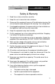
Ad va n c e d S y s t e m Controller AIS-Q572 Safety & Warranty 1. Read these safety instructions carefully. 2. Keep this user's manual for later reference. 3. Disconnect this equipment from any AC outlet before cleaning. Do not use liquid or spray detergents for cleaning. Use a damp cloth. 4. For pluggable equipment, the power outlet must be installed near the equipment and must be easily accessible. 5. Keep this equipment away from humidity. 6. Put this equipment on a firm surface during installation.
Ad va n c e d S y s t e m Controller AIS-Q572 d. The equipment does not work well, or you cannot get it to work according to the user’s manual. e. The equipment has been dropped and damaged. f. The equipment has obvious signs of breakage. 15. DO NOT LEAVE THIS EQUIPMENT IN AN ENVIRONMENT WHERE THE STORAGE TEMPERATURE IS BELOW -20°C (-4°F) OR ABOVE 65°C (149°F). IT MAY DAMAGE THE EQUIPMENT. FCC This device complies with Part 15 FCC Rules.
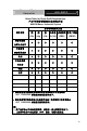
Ad va n c e d S y s t e m Controller AIS-Q572 Below Table for China RoHS Requirements 产品中有毒有害物质或元素名称及含量 AAEON Boxer/ Industrial System 有毒有害物质或元素 部件名称 铅 汞 镉 六价铬 多溴联苯 多溴二苯醚 (Pb) (Hg) (Cd) (Cr(VI)) (PBB) (PBDE) × ○ ○ ○ ○ ○ × ○ ○ ○ ○ ○ × ○ ○ ○ ○ ○ × ○ ○ ○ ○ ○ 硬盘 × ○ ○ ○ ○ ○ 电源 × ○ ○ ○ ○ ○ 印刷电路板 及其电子组件 外部信号 连接器及线材 外壳 中央处理器 与内存 O:表示该有毒有害物质在该部件所有均质材料中的含量均在 SJ/T 11363-2006 标准规定的限量要求以下。 X:表示该有毒有害物质至少在该部件的某一均质材料中的含量超出 SJ/T 11363-2006 标准规定的限量要求。 备注: 一、此产品所标示之环保使用期限,系
Ad va n c e d S y s t e m Controller AIS-Q572 Contents Chapter 1 General Information 1.1 Introduction................................................................ 1-2 1.2 Features .................................................................... 1-3 1.3 Specifications ............................................................ 1-4 Chapter 2 Hardware Installation 2.1 Location of Connectors ............................................. 2-2 2.2 Mechanical Drawing .................................
Ad va n c e d S y s t e m Controller AIS-Q572 2.18 4-Pin ATX Power Connector (ATX2)....................... 2-11 2.19 Riser Card ............................................................... 2-11 2.20 Installing Hard Disk Drive........................................ 2-12 2.21 Optional Accessories Installation……………………2-19 Chapter 3 AMI BIOS Setup 3.1 System Test and Initialization. .................................. 3-2 3.2 AMI BIOS Setup ........................................................
Ad va n c e d S y s t e m Controller AIS-Q572 Chapter 1 General Information Chapter 1 General Information 1- 1
Ad va n c e d S y s t e m Controller AIS-Q572 1.1 Introduction AIS-Q572 adopts the Intel® CoreTM i3/i5/i7 LGA 1156 Processors. The chipset is equipped with Intel® Q57. Moreover, the system memory features two DDR3 1066/1333 MHz DIMM up to 4 GB. It deploys two LAN ports that consist of 10/100/1000Base-TX Ethernet RJ-45 ports. AIS-Q572 condensed appearance features desktop and wallmount form factors that fits nicely into a space-limited environment. This AIS-Q572 equipped with one 3.
Ad va n c e d S y s t e m Controller AIS-Q572 1.2 Features Intel® CoreTM i3/i5/i7 LGA1156 Processor Dual-Channel DDR3 1066/1333 Memory up to 4 GB Intel® Integrated Graphics Engine Support Dual View With VGA & DVI Gigabit Ethernet x 2 3.5” SATA 3.0Gb/s Hard Disk Drive Bay x 1, Slim DVD-RW x 1 (Optional) USB2.
Ad va n c e d S y s t e m Controller AIS-Q572 1.3 Specifications CPU Intel® CoreTM i7/i5/i3 LGA 1156, max. TDP 95W Chipset Intel® Q57 System Memory Up to 4 GB (DDR3 1066/1333 MHz, DIMM x 2) Display VGA 1 DVI 1 HDD 3.5” Hard Disk Drive Bay x 1 Network LAN 10/100/1000Base-TX Ethernet x 2 Front I/O USB Host USB2.0 x 4 Rear I/O USB Host USB2.
Ad va n c e d S y s t e m Controller AIS-Q572 Operating Temperature 32oF ~113oF (0oC~45oC) Storage Temperature -4oF ~140oF (-20oC~60oC) Anti-Vibration 0.5g rms/ 5~500 Hz/ operation Anti-Shock 15G with 11 msec. operation Certification EMC Dimension (W x H x D) CE/FCC 14.17” x 3.47” x 10.04” (360mm x 88mm x 255mm) Gross Weight 15.84 lb (7.
Ad va n c e d S y s t e m Controller AIS-Q572 Chapter 2 Hardware Installation Chapter 2 Hardware Installation 2-1
Ad va n c e d S y s t e m Controller 2.
Ad va n c e d S y s t e m Controller AIS-Q572 2.
Ad va n c e d S y s t e m Controller Chapter 2 Hardware Installation 2-4 AIS-Q572
Ad va n c e d S y s t e m Controller AIS-Q572 2.3 List of Jumpers The board has a number of jumpers that allow you to configure your system to suit your application.
Ad va n c e d S y s t e m Controller AIS-Q572 2.4 List of Connectors The board has a number of connectors that allow you to configure your system to suit your application.
Ad va n c e d S y s t e m Controller AIS-Q572 2.5 Setting Jumpers You configure your card to match the needs of your application by setting jumpers. A jumper is the simplest kind of electric switch. It consists of two metal pins and a small metal clip (often protected by a plastic cover) that slides over the pins to connect them. To “close” a jumper you connect the pins with the clip. To “open” a jumper you remove the clip. Sometimes a jumper will have three pins, labeled 1, 2 and 3.
Ad va n c e d S y s t e m Controller AIS-Q572 2.6 Auto PWRBTN Selection (JP1) JP1 Function 1-2 Use Auto PWRBTN 2-3 Don’t Use Auto PWRBTN (Default) 2.7 CMOS Setting (JP2) JP2 Function 1-2 Normal (Default) 2-3 Clear CMOS 2.8 TPM Setting (JP3) JP3 Function 1-2 Save ME RTC Register (Default) 2-3 Clear ME RTC Register 2.9 BIOS Load Optimized Defaults Selection (JP4) JP4 Function 1-2 Enable (Default) 2-3 Disable 2.
Ad va n c e d S y s t e m Controller AIS-Q572 2.11 Pin Header (USB_F1, USB_F2) Pin Signal Pin Signal 1 +5V 2 GND 3 USBD1- 4 GND 5 USBD1+ 6 USBD2+ 7 GND 8 USBD2- 9 GND 10 +5V 2.12 RS-232 Serial Port Connector (COM1) Pin Signal Pin Signal 1 DCD 2 RXD 3 TXD 4 DTR 5 GND 6 DSR 7 RTS 8 CTS 9 RI 2.
Ad va n c e d S y s t e m Controller 9 +5V AIS-Q572 10 GND 2.15 SATA Connector (SATA 1~4) Pin Signal Pin Signal 1 GND 2 TXP 3 TXN 4 GND 5 RXN 6 RXP 7 GND 2.16 FAN Connector (CPU_FAN, SYS_FAN1~2) Pin Signal Pin Signal 1 GND 2 +12V 3 FAN_TAC 4 FAN_CTL 2.17 24-Pin ATX Power Connector (ATX1) Pin Signal Pin Signal 1 +3.3V 2 +3.3V 3 GND 4 +5V 5 GND 6 +5V 7 GND 8 PWROK 9 +5VSB 10 +12V 11 +12V 12 +3.3V 13 +3.
Ad va n c e d S y s t e m Controller AIS-Q572 2.18 4-Pin ATX Power Connector (ATX2) Pin Signal Pin Signal 1 GND 2 GND 3 +12V 4 +12V 2.
Ad va n c e d S y s t e m Controller AIS-Q572 2.
Ad va n c e d S y s t e m Controller AIS-Q572 Step 3: Pull out the HDD case Chapter 2 Hardware Installation 2-13
Ad va n c e d S y s t e m Controller AIS-Q572 Step 4: Put the HDD to the HDD case and close the upper bracket of the HDD case.
Ad va n c e d S y s t e m Controller AIS-Q572 Step 5: Make sure the dampers are inserted to the right place Chapter 2 Hardware Installation 2-15
Ad va n c e d S y s t e m Controller AIS-Q572 Step 6: Fasten the two screws on the HDD bracket Chapter 2 Hardware Installation 2-16
Ad va n c e d S y s t e m Controller AIS-Q572 Step 7: Plug the SATA cable and power cable Step 8: Finish the installation.
Ad va n c e d S y s t e m Controller Chapter 2 Hardware Installation 2-18 AIS-Q572
Ad va n c e d S y s t e m Controller AIS-Q572 2.
Ad va n c e d S y s t e m Controller HEAT SINK Installation Step 1: Install fan onto heat sink Step 2: Install heat sink onto CPU Chapter 2 Hardware Installation 2-20 AIS-Q572
Ad va n c e d S y s t e m Controller AIS-Q572 Step 3: Insert screws to secure the heat sink Step 4: Secure bracket and fan with the screws Chapter 2 Hardware Installation 2-21
Ad va n c e d S y s t e m Controller AIS-Q572 RAM Installation Step 1: Insert RAM onto slot Step 2: Put a rubber band around RAM to secure it in the slot Chapter 2 Hardware Installation 2-22
Ad va n c e d S y s t e m Controller AIS-Q572 CompactFlash Card Installation Step 1: Secure CompactFlash card by using screws Step 2: Connect the SATA Cable and the Power cable Chapter 2 Hardware Installation 2-23
Ad va n c e d S y s t e m Controller AIS-Q572 DVD-ROM Installation Step 1: Secure DVD ROM onto metal plate Step 2: Secure both sides by installing screws Chapter 2 Hardware Installation 2-24
Ad va n c e d S y s t e m Controller AIS-Q572 Step 3: Install the SATA Cable Step 4: Connect the SATA cable onto the main board Chapter 2 Hardware Installation 2-25
Ad va n c e d S y s t e m Controller AIS-Q572 Step 5: Install the CD bracket with the screws Step 6: Secure the bracket and fan with the screws Chapter 2 Hardware Installation 2-26
Ad va n c e d S y s t e m Controller AIS-Q572 Step 7: The DVD-ROM is shown as below: Chapter 2 Hardware Installation 2-27
Ad va n c e d S y s t e m Controller AIS-Q572 HDD SATA Cable Installation Step 1: You have to press the SATA cable against the Riser Card to make sure the SATA cable has been placed properly. Step 2: The SATA cable will be pulled through bracket hole #2 to avoid damaging the RAM, since the RAM lies directly under bracket hole #1.
Ad va n c e d S y s t e m Controller AIS-Q572 1 2 Step 3: After you pull the SATA cable through bracket hole #2, fasten the four screws of the bracket.
Ad va n c e d S y s t e m Controller AIS-Q572 Chapter 3 AMI BIOS Setup Chapter 3 AMI BIOS Setup 3-1
Ad va n c e d S y s t e m Controller 3.1 AIS-Q572 System Test and Initialization These routines test and initialize board hardware. If the routines encounter an error during the tests, you will either hear a few short beeps or see an error message on the screen. There are two kinds of errors: fatal and non-fatal. The system can usually continue the boot up sequence with non-fatal errors.
Ad va n c e d S y s t e m Controller 3.2 AIS-Q572 AMI BIOS Setup AMI BIOS ROM has a built-in Setup program that allows users to modify the basic system configuration. This type of information is stored in battery-backed CMOS RAM so that it retains the Setup information when the power is turned off. Entering Setup Power on the computer and press or immediately. This will allow you to enter Setup. Main Set the date, use tab to switch between date elements.
Ad va n c e d S y s t e m Controller AIS-Q572 Chapter 4 Driver Installation Chapter 4 Driver Installation 4-1
Ad va n c e d S y s t e m Controller AIS-Q572 The AIS-Q572 comes with a DVD-ROM that contains all drivers your need. Follow the sequence below to install the drivers: Step 1 – Install INF Driver Step 2 – Install VGA Driver Step 3 – Install LAN Driver Step 4 – Install AUDIO Driver Step 5 – Install ME Driver Please read following instructions for detailed installations.
Ad va n c e d S y s t e m Controller AIS-Q572 4.1 Installation: Insert the AIS-Q572 DVD-ROM into the DVD-ROM Drive. And install the drivers from Step 1 to Step 5 in order. Step 1 – Install INF Driver 1. Click on the Step1 - INF folder and then double click on the Setup.exe 2. Follow the instructions that the window shows 3. The system will help you to install the driver automatically Step 2 – Install VGA Driver 1. Click on the Step2 - VGA folder and select the OS your system is 2. Double click on Setup.
Ad va n c e d S y s t e m Controller AIS-Q572 3. Follow the instructions that the window shows 4. The system will help you to install the driver automatically Step 5 – Install ME Driver 1. Click on the Step5 - ME folder and double click on Setup.exe file 2. Follow the instructions that the window shows 3.
Ad va n c e d S y s t e m Controller AIS-Q572 Appendix A Programming the Watchdog Timer Appendix A Programming the Watchdog Timer A-1
Ad va n c e d S y s t e m Controller AIS-Q572 A.1 Programming AIS-Q572 utilizes ITE 8718 chipset as its watchdog timer controller. Below are the procedures to complete its configuration and the AAEON initial watchdog timer program is also attached based on which you can develop customized program to fit your application. Configuring Sequence Description After the hardware reset or power-on reset, the ITE 8718 enters the normal mode with all logical devices disabled except KBC.
Ad va n c e d S y s t e m Controller AIS-Q572 There are three steps to complete the configuration setup: (1) Enter the MB PnP Mode; (2) Modify the data of configuration registers; (3) Exit the MB PnP Mode. Undesired result may occur if the MB PnP Mode is not exited normally. (1) Enter the MB PnP Mode To enter the MB PnP Mode, four special I/O write operations are to be performed during Wait for Key state.
Ad va n c e d S y s t e m Controller AIS-Q572 WatchDog Timer Configuration Registers Configure Control (Index=02h) This register is write only. Its values are not sticky; that is to say, a hardware reset will automatically clear the bits, and does not require the software to clear them.
Ad va n c e d S y s t e m Controller AIS-Q572 Watch Dog Timer Configuration Register (Index=72h Default=001s0000b) Watch Dog Timer Time-Out Value (LSB) Register (Index=73h Default=38h) Watch Dog Timer Time-Out Value (MSB) Register (Index=74h Default=00h) Appendix A Programming the Watchdog Timer A-5
Ad va n c e d S y s t e m Controller AIS-Q572 A.2 ITE8718 Watchdog Timer Initial Program .MODEL SMALL .CODE Main: CALL Enter_Configuration_mode CALL Check_Chip mov cl, 7 call Set_Logic_Device ;time setting mov cl, 10 ; 10 Sec dec al Watch_Dog_Setting: ;Timer setting mov al, cl mov cl, 73h call Superio_Set_Reg ;Clear by keyboard or mouse interrupt mov al, 0f0h mov cl, 71h call Superio_Set_Reg ;unit is second.
Ad va n c e d S y s t e m Controller AIS-Q572 call Superio_Set_Reg ; game port enable mov cl, 9 call Set_Logic_Device Initial_OK: CALL Exit_Configuration_mode MOV AH,4Ch INT 21h Enter_Configuration_Mode PROC NEAR MOV SI,WORD PTR CS:[Offset Cfg_Port] MOV DX,02Eh MOV CX,04h Init_1: MOV AL,BYTE PTR CS:[SI] OUT DX,AL INC SI LOOP Init_1 RET Enter_Configuration_Mode ENDP Exit_Configuration_Mode PROC NEAR MOV AX,0202h Appendix A Programming the Watchdog Timer A-7
Ad va n c e d S y s t e m Controller CALL Write_Configuration_Data RET Exit_Configuration_Mode ENDP Check_Chip PROC NEAR MOV AL,20h CALL Read_Configuration_Data CMP AL,87h JNE Not_Initial MOV AL,21h CALL Read_Configuration_Data CMP AL,81h JNE Not_Initial Need_Initial: STC RET Not_Initial: CLC RET Check_Chip ENDP Read_Configuration_Data PROC NEAR MOV DX,WORD PTR CS:[Cfg_Port+04h] Appendix A Programming the Watchdog Timer A-8 AIS-Q572
Ad va n c e d S y s t e m Controller AIS-Q572 OUT DX,AL MOV DX,WORD PTR CS:[Cfg_Port+06h] IN AL,DX RET Read_Configuration_Data ENDP Write_Configuration_Data PROC NEAR MOV DX,WORD PTR CS:[Cfg_Port+04h] OUT DX,AL XCHG AL,AH MOV DX,WORD PTR CS:[Cfg_Port+06h] OUT DX,AL RET Write_Configuration_Data ENDP Superio_Set_Reg proc near push ax MOV DX,WORD PTR CS:[Cfg_Port+04h] mov al,cl out dx,al pop ax inc dx out dx,al ret Superio_Set_Reg endp.
Ad va n c e d S y s t e m Controller Set_Logic_Device proc AIS-Q572 near push ax push cx xchg al,cl mov cl,07h call Superio_Set_Reg pop cx pop ax ret Set_Logic_Device endp ;Select 02Eh->Index Port, 02Fh->Data Port Cfg_Port DB 087h,001h,055h,055h DW 02Eh,02Fh END Main Note: Interrupt level mapping 0Fh-Dh: not valid 0Ch: IRQ12 . .
Ad va n c e d S y s t e m Controller AIS-Q572 Appendix B I/O Information Appendix B I/O Information B-1
Ad va n c e d S y s t e m Controller B.
Ad va n c e d S y s t e m Controller AIS-Q572 B.2 1st MB Memory Address Map B.3 IRQ Mapping Chart B.