Industrial Motherboard EMB-H61B EMB-H61B Manual 1st Ed.
Industrial Motherboard EMB-H61B Copyright Notice This document is copyrighted, 2012. All rights are reserved. The original manufacturer reserves the right to make improvements to the products described in this manual at any time without notice. No part of this manual may be reproduced, copied, translated, or transmitted in any form or by any means without the prior written permission of the original manufacturer. Information provided in this manual is intended to be accurate and reliable.
Industrial Motherboard EMB-H61B Acknowledgments All other products’ name or trademarks are properties of their respective owners. AMI is a trademark of American Megatrends Inc. CompactFlash™ is a trademark of the Compact Flash Association. Intel is a trademark of Intel Corporation. Microsoft Windows is a registered trademark of Microsoft Corp. ITE is a trademark of Integrated Technology Express, Inc.
Industrial Motherboard EMB-H61B Packing List Before you begin installing your card, please make sure that the following materials have been shipped: 1 Industrial Motherboard 1 SATA Cable 1 SATA Power Cable 1 Metal I/O Bracket 1 DVD-ROM for Manual (in PDF Format) and Drivers If any of these items should be missing or damaged, please contact your distributor or sales representative immediately.
Industrial Motherboard EMB-H61B Contents Chapter 1 General Information 1.1 Features .................................................................... 1-2 1.2 Specifications ............................................................ 1-3 Chapter 2 Quick Installation Guide 2.1 Safety Precautions .................................................... 2-2 2.2 Location of Connectors and Jumpers ....................... 2-3 2.3 Mechanical Drawing .................................................. 2-5 2.
Industrial Motherboard EMB-H61B 2.16 Digital I/O Connector (DIO) ..................................... 2-12 2.17 Front Panel Connector (F_PANEL) ......................... 2-13 2.18 Inverter Connector (INV) ......................................... 2-13 2.19 LVDS Panel Signal Connector (LVDS) ................... 2-13 2.20 SATA Power Connector (PWR1) ............................ 2-15 2.21 FAN Connector (S_FAN1 / S_FAN2) ...................... 2-15 2.22 Internal USB 2.0 Connector (USB910) ...................
Industrial Motherboard EMB-H61B Chapter 1 General Information Chapter 1 General Information 1- 1
Industrial Motherboard EMB-H61B 1.1 Features ® rd nd Intel Socket 1155 for 3 /2 Generation Core™ i7/ i5/ i3/ Pentium® / Celeron® Processors (Supports Intel® 22/32 nm CPU up to 65W) 2 x 204-pin Dual-Channel DDR3 1333/1066MHz SO-DIMM Up to 16GB ® Intel integrated Graphics Engine Supports Dual View by VGA, HDMI x 2, LVDS Realtek PCI-Express Gigabit Ethernet x 2 SATA 3.0Gb/s x 2 & CF Socket x 1 (Supports Both CF-SATA Card and CF Type 1 USB 2.0 x 8 & COM x 6 PCI-Express 2.
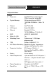
Industrial Motherboard EMB-H61B 1.2 Specifications System Processor ® nd rd Intel 2 /3 generation Core™ i7/i5/i3 Processor, up to 65W System Memory 204-pin dual-channel DDR3 1333/1066 SODIMM x 2, Max. 16 GB Chipset Intel H61 (B3) I/O Chipset Fintek F81866D-I Ethernet Realtek 8111F for 10/100/1000Base-T, RJ-45 x 2 BIOS Wake On LAN AMI BIOS, 64Mb ROM Yes Watchdog Timer System reset: 1~255 steps programmable TPM Infineon SLB9635 TT 1.
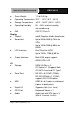
Industrial Motherboard EMB-H61B Gross Weight Operating Temperature 32°F ~ 131°F (0°C ~ 55°C) Storage Temperature -40°F ~ 185°F (-40°C ~ 85°C) Operating Humidity 0% ~ 90% relative humidity, non-condensing EMI CE/FCC Class A Display Chipset Resolution 1.1 lb (0.
Industrial Motherboard EMB-H61B Chapter 2 Quick Installation Guide Chapter 2 Quick Installation Guide 2 - 1
Industrial Motherboard EMB-H61B 2.1 Safety Precautions Always completely disconnect the power cord from your board whenever you are working on it. Do not make connections while the power is on, because a sudden rush of power can damage sensitive electronic components. Always ground yourself to remove any static charge before touching the board. Modern electronic devices are very sensitive to static electric charges. Use a grounding wrist strap at all times.
Industrial Motherboard EMB-H61B 2.
Industrial Motherboard Solder Side Chapter 2 Quick Installation Guide 2 - 4 EMB-H61B
Industrial Motherboard EMB-H61B 2.
Industrial Motherboard Solder Side Chapter 2 Quick Installation Guide 2 - 6 EMB-H61B
Industrial Motherboard EMB-H61B 2.4 List of Jumpers The board has a number of jumpers that allow you to configure your system to suit your application. The table below shows the function of each of the board's jumpers: Label Function CLRTC Clear CMOS J1 LVDS Panel Voltage Selection J2 Inverter Voltage Selection J3 Mode Selection for Back Light Control of Inverter J4 AT/ATX mode Selection J5 COM1 Ring/+5V/+12V Selection 2.
Industrial Motherboard EMB-H61B COM5 COM5 Connector COM6 COM6 Connector DEBUG Debug Connector DIMM_A1 DIMM1 Slot DIMM_B1 DIMM2 Slot DIO Digital I/O Connector F_PANEL Front Panel Connector HDMI1 HDMI Connector HDMI2 HDMI Connector INV Inverter Connector KBMS_USB56 PS/2 KB&MS and USB5/6 Connector LAN1_ USB12 LAN1 & USB1/2 Connector LAN2_ USB34 LAN2 & USB3/4 Connector LGA1 CPU Socket - LGA-1155P LVDS LVDS Panel Signal Connector MINICARD Mini Card socket PCIEX4 PCI Express x4
Industrial Motherboard EMB-H61B 2.6 Setting Jumpers You configure your card to match the needs of your application by setting jumpers. A jumper is the simplest kind of electric switch. It consists of two metal pins and a small metal clip (often protected by a plastic cover) that slides over the pins to connect them. To “close” a jumper you connect the pins with the clip. To “open” a jumper you remove the clip. Sometimes a jumper will have three pins, labeled 1, 2 and 3.
Industrial Motherboard EMB-H61B 2.7 Clear CMOS (CLRTC) CLRTC Function 1-2 RTC Batt. 2-3 Clear CMOS 2.8 LVDS Panel Voltage Selection (J1) J1 Function 1-2 +5V 2-3 +3.3V (Default) 2.9 Inverter Voltage Selection (J2) J2 Function 1-2 +12V 2-3 +5V (Default) 2.10 Mode Selection for Back Light Control of Inverter (J3) J3 Function 1-2 DC Voltage Control (Default) 2-3 PWM Control 2.
Industrial Motherboard EMB-H61B 2.12 COM1 Ring/+5V/+12V Selection (J5) J5 Function 1-2 +12V 3-4 +5V 5-6 Ring (Default) 2.13 Internal COM Serial Port Connector (COM2 ~ COM6) Pin Signal Pin Signal 1 DCD 2 RXD 3 TXD 4 DTR 5 GND 6 DSR 7 RTS 8 CTS 9 RI 10 (NC) 2.14 PS/2 Keyboard/Mouse Connector with Dock USB 2.
Industrial Motherboard EMB-H61B 15 GND 16 GND 17 GND 18 GND 2.15 1000Base-T Ethernet Connector with Dock USB 2.
Industrial Motherboard EMB-H61B 3 DIO_I#3 (DIO_P#3) 4 DIO_I#4 (DIO_P#4) 5 DIO_O#1 (DIO_P#5) 6 DIO_O#2 (DIO_P#6) 7 DIO_O#3 (DIO_P#7) 8 DIO_O#4 (DIO_P#8) 9 +5V 10 GND 2.17 Front Panel Connector (F_PANEL) Pin Signal Pin Signal 1 HDLED+ 2 PLED+ 3 HDLED- 4 PLED- 5 GND 6 PANSWH# 7 HWRST# 8 GND 9 (NC) 10 (kill pin) 2.18 Inverter Connector (INV) Pin Signal 1 Inverter VCC 3 Back Light Control 5 GND 7 GND 9 Back Light Enable 2.
Industrial Motherboard EMB-H61B 25 LVDS1_D3- 26 LVDS1_D3+ 23 LVDS1_D2- 24 LVDS1_D2+ 21 LVDS1_D1- 22 LVDS1_D1+ 19 LVDS1_D0- 20 LVDS1_D0+ 17 EDID_Data 18 EDID_Clk 15 LVDS0_D3- 16 LVDS0_D3+ 13 LVDS0_D2- 14 LVDS0_D2+ 11 LVDS0_D1- 12 LVDS0_D1+ 9 LVDS0_D0- 10 LVDS0_D0+ 7 LVDS VCC 8 GND 5 LVDS0_CLK- 6 LVDS0_CLK+ 3 LVDS VCC 4 GND 1 LVDS Panel Enable 2 Backlight Control for DC mode NOTE: LVDS connector Vendor: PINREX; Model: 712-76-30GWR8.
Industrial Motherboard EMB-H61B 2.20 SATA Power Connector (PWR1) Pin Signal 1 +5V 2 GND 3 GND 4 +12V 2.21 FAN Connector (S_FAN1 / S_FAN2) Pin Signal 1 PWM 2 SENSE 3 VCC 4 GND 2.22 Internal USB 2.
Industrial Motherboard EMB-H61B Chapter 3 AMI BIOS Setup Chapter 3 AMI BIOS Setup 3-1
Industrial Motherboard 3.1 EMB-H61B System Test and Initialization These routines test and initialize board hardware. If the routines encounter an error during the tests, you will either hear a few short beeps or see an error message on the screen. There are two kinds of errors: fatal and non-fatal. The system can usually continue the boot up sequence with non-fatal errors.
Industrial Motherboard 3.2 EMB-H61B AMI BIOS Setup AMI BIOS ROM has a built-in Setup program that allows users to modify the basic system configuration. This type of information is stored in battery-backed CMOS RAM so that it retains the Setup information when the power is turned off. Entering Setup Power on the computer and press or immediately. This will allow you to enter Setup. Main Set the date, use tab to switch between date elements.
Industrial Motherboard Setup Menu Setup submenu: Main Setup submenu: Advanced Chapter 3 AMI BIOS Setup 3-4 EMB-H61B
Industrial Motherboard EMB-H61B ACPI Settings Options summary : Suspend mode S1 (CPU Stop Clock) S3 (Suspend to Optimal Default, Failsafe RAM) Default Select the ACPI state used for System Suspend Chapter 3 AMI BIOS Setup 3-5
Industrial Motherboard EMB-H61B Trusted Computing Options summary: Security Disabled Optimal Default, Failsafe Default Device Support Enabled En/Disable TPM support. TPM State Disabled Optimal Default, Failsafe Default Enabled En/Disable TPM State.
Industrial Motherboard EMB-H61B Enable Take Ownership Disable Take Ownership TPM Clear Select one-time TPM operation. Item value returns to ‘None’ after next POST.
Industrial Motherboard CPU Configuration Chapter 3 AMI BIOS Setup 3-8 EMB-H61B
Industrial Motherboard EMB-H61B Options summary : Hyper-Threading Disabled Enabled Optimal Default, Failsafe Default En/Disable CPU Hyper-Threading function Intel Disabled Virtualization Technology Optimal Default, Failsafe Default Enabled En/Disable Turbo Mode (Turbo mode should be disabled when using 55W or 65W CPU) Turbo Mode Disabled Enabled Optimal Default, Failsafe Default En/Disable Intel VT-x function Chapter 3 AMI BIOS Setup 3-9
Industrial Motherboard EMB-H61B Digital IO Configuration Options summary : DIO_P# 1-4 Input Optimal Default, Failsafe Default Output Set GPIO as Input or Output DIO_P# 5-8 Input Output Optimal Default, Failsafe Default Set GPIO as Input or Output Chapter 3 AMI BIOS Setup 3-10
Industrial Motherboard DIO_P# 1-8 Low Direction High EMB-H61B Optimal Default, Failsafe Default Set GPIO Output as Hi or Low.
Industrial Motherboard EMB-H61B AHCI IDE: Configure SATA controllers as legacy IDE AHCI: Configure SATA controllers to operate in AHCI mode SATA Controller Speed Gen1 Default Gen2 Select serial ATA Controller Speed Port 0, 1, 4, 5 Hot Plug Disabled Enabled Default Disabled Default Enabled En/Disable Hot Plug feature.
Industrial Motherboard EMB-H61B USB Configuration Options summary: Legacy USB Support Enabled Optimal Default, Failsafe Default Disabled Auto Enables BIOS Support for Legacy USB Support. When enabled, USB can be functional in legacy environment like DOS.
Industrial Motherboard EMB-H61B Forced FDD Hard Disk CDROM If Auto. USB devices less than 530MB will be emulated as Floppy and remaining as Floppy and remaining as hard drive. Forced FDD option can be used to force a HDD formatted drive to boot as FDD(Ex.
Industrial Motherboard EMB-H61B Serial Port Configuration Chapter 3 AMI BIOS Setup 3-15
Industrial Motherboard EMB-H61B Options summary : F81866 ERP Function Disabled Default Enabled Enable or Disable ERP function. Serial Port Disabled Enabled Default Allows BIOS to En/Disable correspond serial port. Device Mode RS232 Default RS422 RS485 Select working model. Change Settings Auto (Serial Port 1) Default IO=3F8h; IRQ=4; IO=3F8h; IRQ=3,4; IO=2F8h; IRQ=3,4; IO=3E8h; IRQ=10,11; IO=2E8h; IRQ=10,11 Allows BIOS to Select Serial Port resource.
Industrial Motherboard EMB-H61B IO=2E8h; IRQ=10,11 Allows BIOS to Select Serial Port resource. Change Settings Auto (Serial Port 3) Default IO=3E8h; IRQ=10,11; IO=2E8h; IRQ=10,11; IO=2D0h; IRQ=10,11; IO=2D8h; IRQ=10,11 Allows BIOS to Select Serial Port resource. Change Settings Auto (Serial Port 4) Default IO=2E8h; IRQ=10,11; IO=3E8h; IRQ=10,11; IO=2D0h; IRQ=10,11; IO=2D8h; IRQ=10,11; Allows BIOS to Select Serial Port resource.
Industrial Motherboard EMB-H61B IO=2D8h; IRQ=10,11 Allows BIOS to Select Serial Port resource. Device Mode Disable IR1 function Enable IR1 function, active pulse 1.6us Enable IR1 function, active pulse 3/16 bit time Select Device Mode.
Industrial Motherboard EMB-H61B Smart Fan Mode Configuration Chapter 3 AMI BIOS Setup 3-19
Industrial Motherboard EMB-H61B Options summary : SYS/CPU Smart Auto by RPM Fan Control Auto by Duty-Cycle Default Manual by RPM Manual by Duty-Cycle Select CPU Smart FAN mode Auto by RPM: Automatically controlling the fan to maintain target Fan Speed. Auto by Duty-Cycle: Automatically controlling the fan to maintain target temperature. Manual by RPM: Manually controlling the fan with a given Fan Speed. Manual by Duty-Cycle: Manually controlling the fan with a given control PWM. Target Temp.
Industrial Motherboard EMB-H61B Setup submenu: Chipset PCH-IO Configuration Chapter 3 AMI BIOS Setup 3-21
Industrial Motherboard EMB-H61B Options summary : Power Mode ATX Type Optimal Default, Failsafe Default AT Type Select Power Mode. Restore on AC Power Power Off Loss Default Power On Last State Select the action system to take when restoring from power loss. ATX Type: Default Power Off AT Type: Default Power On JMB 386 ATA Controller Disabled Enabled Optimal Default, Failsafe Default (support CF-PATA) Enabling/Disabling PCI-E to CF-PATA controller.
Industrial Motherboard EMB-H61B System Agent (SA) Configuration Options summary : PCIE x 4 Gen Speed Gen1 Optimal Default, Failsafe Default Gen2 Select PCI Express Gen speed.
Industrial Motherboard EMB-H61B Graphics Configuration Options summary : Primary Display Auto Default IGFX PEG Select which of IGFX/PEG Graphics device should be Primary Display. Internal Graphics Auto Default Disable Enable Keep IGD enabled based on the setup options.
Industrial Motherboard EMB-H61B Select the GTT Size. Aperture Size 128MB 256MB Default 512MB Select the Aperture Size. DVMT Pre-Allocated 32M 64M Default 96M 128M 160M 192M 224M 256M 288M 320M 352M 384M 416M 448M 480M 512M 1024M Select DVMT 5.0 Pre-Allocated(Fixed) Graphics Memory size used by the Internal Graphics Device.
Industrial Motherboard DVMT Total Gfx Mem EMB-H61B 128M 256M MAX Default Select DVMT Total Graphics Memory Primary IGFX Boot Display AUTO Default CRT HDMI-1 HDMI-2 DVI Select the Video Device which will be activated during POST. For dual-display, select “Auto”. Note: The platform only supports single display in legacy environment (DOS).
Industrial Motherboard EMB-H61B 1280x768 24Bit 1366x768 24Bit 1440x900 48Bit 1920x1080 48Bit 1280x1024 18Bit 1280x1024 24Bit Select LCD panel used by Internal Graphics Device by selecting the appropriate setup item. CH7511B Baclight DC Mode Control Mode PWM Mode Default Select Ch7511B Backlight Control by DC or PWM Mode. Brightness setting 100% Default 75% 50% 25% 0% CH7511B Brightness Setting. Backlight Control NORMAL INVERT Default Select Ch7511B Backlight Control way.
Industrial Motherboard EMB-H61B Setup submenu: Boot Options summary : Bootup NumLock On Default State Off Select the keyboard NumLock state. Quiet Boot Disabled Default Enabled En/Disable showing boot logo. Launch RTL8111F Disabled PXE OpROM Enabled Default Enable or Disable Legacy Boot Option for RTL811E.
Industrial Motherboard GateA20 Active Upon Request EMB-H61B Default Always UPON REQUEST – GA20 can be disabled using BIOS services. ALWAYS – do not allow disabling GA20; this option is useful when any RT code is executed above 1MB. Option ROM Force BIOS Default Messages Keep Current Set display mode for Option ROM. INT19 Trap Response Immediate Default Postponed BIOS reaction on INT19 trapping by Option ROM: IMMEDIATE – execute the trap right away; POSTPONED – execute the trap during legacy boot.
Industrial Motherboard EMB-H61B Setup submenu: Security Change User/Supervisor Password You can install a Supervisor password, and if you install a supervisor password, you can then install a user password. A user password does not provide access to many of the features in the Setup utility. If you highlight these items and press Enter, a dialog box appears which lets you enter a password. numbers. You can enter no more than six letters or Press Enter after you have typed in the password.
Industrial Motherboard EMB-H61B box press Enter to disable password protection.
Industrial Motherboard EMB-H61B Chapter 4 Driver Installation Chapter 4 Driver Installation 4-1
Industrial Motherboard EMB-H61B Follow the sequence below to install the drivers: Step 1 – Install Chipset Driver Step 2 – Install VGA Driver Step 3 – Install LAN Driver Step 4 – Install AUDIO Driver Step 5 – Install AHCI Driver Step 6 – Install ME Driver Step 7 – Install TPM Driver Step 8 – Install Serial Port Driver (Optional) Please read following instructions for detailed installations.
Industrial Motherboard EMB-H61B 4.1 Installation: Insert DVD-ROM into the DVD-ROM Drive. And install the drivers from Step 1 to Step 8 in order. Step 1 – Install Chipset Driver 1. Click on the Step1 - Chipset folder and then double click on the Setup.exe 2. Follow the instructions that the window shows 3. The system will help you to install the driver automatically Step 2 – Install VGA Driver 1. Click on the Step 2 - VGA folder and select the OS your system is 2. Double click on Setup.
Industrial Motherboard EMB-H61B 2. Follow the instructions that the window shows 3. The system will help you to install the driver automatically Step 5 – Install AHCI Driver 1. Click on the Step 5 - AHCI folder 2. For XP, please copy the files to Floppy folder and press F6 to install ; for other OS, system will install the driver automatically. Step 6 – Install ME Driver 1. Click on the Step 6 - ME folder and select the OS your system is 2. Double click on setup.exe file located in each OS folder 3.
Industrial Motherboard EMB-H61B Chapter4 Drivers Installation 4-5
Industrial Motherboard Chapter 4 Driver Installation 4-6 EMB-H61B
Industrial Motherboard EMB-H61B Chapter4 Drivers Installation 4-7
Industrial Motherboard EMB-H61B Appendix A Programming the Watchdog Timer Appendix A Programming the Watchdog Timer A-1
Industrial Motherboard EMB-H61B A.1 Watchdog Timer Initial Program Table 1 : SuperIO relative register table Default Value Index 0x2E(Note1) Data 0x2F(Note2) Note SIO MB PnP Mode Index Register 0x2E or 0x4E SIO MB PnP Mode Data Register 0x2F or 0x4F Table 2 : Watchdog relative register table LDN Register BitNum Value Note Time of watchdog Timer Counter timer 0x07(Note3) 0xF6(Note4) (Note24) (0~255) This register is byte access Counting Unit Watchdog Enable Timeout Status Select time unit.
Industrial Motherboard EMB-H61B ************************************************************************************ // SuperIO relative definition (Please reference to Table 1) #define byte SIOIndex //This parameter is represented from Note1 #define byte SIOData //This parameter is represented from Note2 #define void IOWriteByte(byte IOPort, byte Value); #define byte IOReadByte(byte IOPort); // Watch Dog relative definition (Please reference to Table 2) #define byte TimerLDN //This parameter is represent
Industrial Motherboard EMB-H61B ************************************************************************************ VOID Main(){ // Procedure : AaeonWDTConfig // (byte)Timer : Time of WDT timer.(0x00~0xFF) // (boolean)Unit : Select time unit(0: second, 1: minute). AaeonWDTConfig(); // Procedure : AaeonWDTEnable // This procudure will enable the WDT counting.
Industrial Motherboard EMB-H61B ************************************************************************************ // Procedure : AaeonWDTEnable VOID AaeonWDTEnable (){ WDTEnableDisable(EnableLDN, EnableReg, EnableBit, 1); } // Procedure : AaeonWDTConfig VOID AaeonWDTConfig (){ // Disable WDT counting WDTEnableDisable(EnableLDN, EnableReg, EnableBit, 0); // Clear Watchdog Timeout Status WDTClearTimeoutStatus(); // WDT relative parameter setting WDTParameterSetting(); } VOID WDTEnableDisable(byte LDN, by
Industrial Motherboard EMB-H61B ************************************************************************************ VOID SIOEnterMBPnPMode(){ IOWriteByte(SIOIndex, 0x87); IOWriteByte(SIOIndex, 0x87); } VOID SIOExitMBPnPMode(){ IOWriteByte(SIOIndex, 0xAA); } VOID SIOSelectLDN(byte LDN){ IOWriteByte(SIOIndex, 0x07); // SIO LDN Register Offset = 0x07 IOWriteByte(SIOData, LDN); } VOID SIOBitSet(byte LDN, byte Register, byte BitNum, byte Value){ Byte TmpValue; SIOEnterMBPnPMode(); SIOSelectLDN(byte LDN); IOWr
Industrial Motherboard EMB-H61B Appendix B Mating Connector Appendix B Mating Connector B - 1
Industrial Motherboard EMB-H61A BSupport up to 65W.1 List of Mating Connectors and Cables The table notes mating connectors and available cables. Connector Label Function Mating Connector Vendor Model no ATX12V ATX 4P Power Connector PINREX 740-41-04TWC0 AUDIO Audio jack Connector JA33331-2119-4F FOXCONN BATTERY RTC - Coin Battery Holder LOTES KB7566BP5L CF-PATA_ CF CONN CF-SATA 50P,0.635mm,REVERS,S MT COM1 D-SUB 9P,M,R/A,G/F,HIGH RISE COM2 Int. COM2 RS-232 Serial Port Connector COM3 Int.
Industrial Motherboard HDMI1 HDMI2 INV EMB-H61B HDMI CON 19P,0.5MM,A SINBON TYPE,R/A HDMI CON 19P,0.5MM,A SINBON TYPE,R/A Inverter Connector PINREX 1165-92104-24D 1165-92104-24D 721-81-05TW00 KBMS_US PS/2 Keyboard/Mouse B56 Connector with Dock USB 2.0 Connector LAN1_ 1000 Base-T Ethernet USB12 Connector with Dock USB 2.0 Connector LAN2_ 1000 Base-T Ethernet USB34 Connector with Dock USB 2.
Industrial Motherboard EMB-H61B Appendix C Electrical Specifications for I/O Ports Appendix C Electrical Specifications for I/O Ports C-1
Industrial Motherboard EMB-H61B C.1 DIO Programming EMB-H61B utilizes FINTEK 81866 chipset as its Digital I/O controller. Below are the procedures to complete its configuration and the AAEON initial watchdog timer program is also attached based on which you can develop customized program to fit your application. There are three steps to complete the configuration setup: (1) Enter the MB PnP Mode; (2) Modify the data of configuration registers; (3) Exit the MB PnP Mode.
Industrial Motherboard EMB-H61B C.
Industrial Motherboard EMB-H61B C.
Industrial Motherboard EMB-H61B ************************************************************************************ // Digital Output control relative definition (Please reference to Table 3) #define byte DOutput1LDN // This parameter is represented from Note27 #define byte DOutput1Reg // This parameter is represented from Note28 #define byte DOutput1Bit // This parameter is represented from Note29 #define byte DOutput1Val // This parameter is represented from Note30 #define byte DOutput2LDN // This para
Industrial Motherboard EMB-H61B ************************************************************************************ VOID Main(){ Boolean PinStatus ; // Procedure : AaeonReadPinStatus // Input : // Example, Read Digital I/O Pin 3 status // Output : // InputStatus : // 0: Digital I/O Pin level is low // 1: Digital I/O Pin level is High PinStatus = AaeonReadPinStatus(DInput3LDN, DInput3Reg, DInput3Bit); // Procedure : AaeonSetOutputLevel // Input : // Example, Set Digital I/O Pin 6 level AaeonSetOutputLevel
Industrial Motherboard EMB-H61B ************************************************************************************ Boolean AaeonReadPinStatus(byte LDN, byte Register, byte BitNum){ Boolean PinStatus ; PinStatus = SIOBitRead(LDN, Register, BitNum); Return PinStatus ; } VOID AaeonSetOutputLevel(byte LDN, byte Register, byte BitNum, byte Value){ ConfigToOutputMode(LDN, Register, BitNum); SIOBitSet(LDN, Register, BitNum, Value); } *****************************************************************************
Industrial Motherboard EMB-H61B ************************************************************************************ VOID SIOEnterMBPnPMode(){ IOWriteByte(SIOIndex, 0x87); IOWriteByte(SIOIndex, 0x87); } VOID SIOExitMBPnPMode(){ IOWriteByte(SIOIndex, 0xAA); } VOID SIOSelectLDN(byte LDN){ IOWriteByte(SIOIndex, 0x07); // SIO LDN Register Offset = 0x07 IOWriteByte(SIOData, LDN); } VOID SIOBitSet(byte LDN, byte Register, byte BitNum, byte Value){ Byte TmpValue; SIOEnterMBPnPMode(); SIOSelectLDN(byte LDN); IOWr
Industrial Motherboard EMB-H61B ************************************************************************************ Boolean SIOBitRead(byte LDN, byte Register, byte BitNum){ Byte TmpValue; SIOEnterMBPnPMode(); SIOSelectLDN(LDN); IOWriteByte(SIOIndex, Register); TmpValue = IOReadByte(SIOData); TmpValue &= (1 << BitNum); SIOExitMBPnPMode(); If(TmpValue == 0) Return 0; Return 1; } VOID ConfigToOutputMode(byte LDN, byte Register, byte BitNum){ Byte TmpValue, OutputEnableReg; OutputEnableReg = Register-1; SIO