Industrial Motherboard EMB-KB1
E8620 First Edition October 2013 Copyright Notice This document is copyrighted, 2013. All rights are reserved. The original manufacturer reserves the right to make improvements to the products described in this manual at any time without notice. No part of this manual may be reproduced, copied, translated, or transmitted in any form or by any means without the prior written permission of the original manufacturer. Information provided in this manual is intended to be accurate and reliable.
Contents Chapter 1 Product overview 1.1 Package contents.......................................................................... 1-1 1.3 Specifications................................................................................ 1-2 1.2 Features......................................................................................... 1-1 Chapter 2 Motherboard information 2.1 Before you proceed...................................................................... 2-1 2.3 Screw size.........
iv
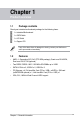
Chapter 1 Product overview 1.1 Package contents Check your industrial motherboard package for the following items. 1 x Industrial Motherboard 1 x SATA Cable 1 x I/O Shield 1 x Support CD If any of the above items is damaged or missing, contact your distributor or sales representative immediately. 1.2 • • • • • Features AMD 1 Generation APU SoC (FT3 BGA package), Quad-core GX-420CA, Dual-core GX-217GA (optional) ® st Two DDR3 / DDR3L 1600 / 1333 MHz SO-DIMMs up to 16GB SATA 6.0 Gb/s x 2, USB3.
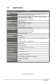
1.3 Specifications SYSTEM Form factor CPU Mini-ITX Memory 2 x SO-DIMM (8GB per DIMM), max.
Chipset Resolution Output interface DISPLAY Quad-core GX-420CA / Dual-core GX-217GA (Integrated) Up to 1920x1200@60Hz for VGA Up to 1920x1200@60Hz for DVI Up to 1920x1080@60Hz, Dual Channel 18/24-bit 1 x LVDS 1 x VGA 1 x DVI I/O Storage 2 x SATA 6.0Gb/s ports Serial port 1 x RS-232/422/485 supports 5V/12V/RI option (COM1 on rear I/O) USB Fan RTC Keyboard/Mouse Audio Ethernet 1 x SATA power connector 5 x RS-232 (COM2 on rear I/O, COM3-COM6 for box header) 2 x USB3.
1-4 EMB-KB1
Chapter 2 Motherboard information 2.1 Before you proceed Take note of the following precautions before you install motherboard components or change any motherboard settings. CAUTION! • Unplug the power cord from the wall socket before touching any component. • Before handling components, use a grounded wrist strap or touch a safely grounded object or a metal object, such as the power supply case, to avoid damaging them due to static electricity.
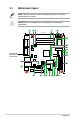
2.2 Motherboard layout NOTE: Place four screws into the holes indicated by circles to secure the motherboard to the chassis. CAUTION! Do not overtighten the screws! Doing so can damage the motherboard. 1 2 3 4 5 17.0cm(6.
Connectors/Jumpers/Slots 1. LVDS connector (30-pin LVDS1) 2. COM1 Ring/+5V/+12V selection (6-pin J4) 3. ATX power connectors (24-pin EATXPWR1, 4-pin EATX_PWR2) 4. SO-DIMM memory slots 5. CPU and chassis fan connectors (4-pin CPU_FAN, 4-pin CHA_FAN) Page 2-19 2-10 2-14 2-6 2-15 6. 7. 8. 9. 10. 11. 12. 13. 14. 15. 16. 17. 18. 19. 20. 21.
2.3 2.3.
2.3.
2.4 AMD Accelerated Processing Unit The motherboard comes with an AMD® 1st Generation APU SoC Quad Core GX420CA, Dual-core GX-217GA (optional). APU EMB-KB1 APU 2.5 System memory This motherboard comes with two Double Data Rate 3 / Double Data Rate 3 Low Voltage (DDR3/DD3L) Small Outline Dual Inline Memory Modules (SO-DIMM) socket.
2.5.
2.6 1. Jumpers Clear RTC RAM (CLRTC) This jumper allows you to clear the Real Time Clock (RTC) RAM in CMOS. You can clear the CMOS memory of system setup parameters by erasing the CMOS RTC RAM data. The onboard button cell battery powers the RAM data in CMOS, which include system setup information such as system passwords. 2 1 2 3 CLRTC Normal (Default) Clear RTC1 EMB-KB1 Clear RTC RAM To erase the RTC RAM: 1. Turn OFF the computer and unplug the power cord. 2.
2. LVDS panel voltage selection (3-pin J1) J1 1 2 2 +5V +3V (Default) 3 EMB-KB1 LVDS Panel Voltage Selection Setting Pins +5V 1-2 +3.3V 2-3 3.
4. Inverter Backlight Control of Inverter selector (3-pin J3) 1 2 J3 2 3 DC CTL PWM CTL (Default) EMB-KB1 Mode Selection for Backlight Control of Inverter Setting Pins DC Voltage Control 1-2 PWM Control (Default) 2-3 5.
2.7 1. Onboard LEDs Standby Power LED The motherboard comes with a standby power LED that lights up to indicate that the system is ON, in sleep mode, or in soft-off mode. This is a reminder that you should shut down the system and unplug the power cable before removing or plugging in any motherboard component. The illustration below shows the location of the onboard LED.
2.8 Connectors 2.8.1 1. 2. 3. Rear panel connectors 1 2 3 11 10 9 4 8 5 7 6 PS/2 Mouse port (green). This port is for a PS/2 mouse. Serial port (COM1). This port connects a modem, or other devices that conform with serial specification. This serial port also supports RS-232 / RS422 / RS-485 connections. Pin Signal Pin Signal 1 DCD (422TXD-/485DATA-) 2 RXD (422RXD+) 3 TXD (422TXD+/485DATA+) 4 DTR (422RXD-) 5 GND 6 DSR 7 RTS 8 CTS 9 RI/+12V/+5V 10 N.C.
4. LAN1~2 (RJ-45) ports. These ports allow Gigabit connection to a Local Area Network (LAN) through a network hub. Refer to the table below for the LAN2 port LED indications. LAN port LED indications ACT/LINK LED Status Description OFF No link 5. 6. 7. ORANGE Linked BLINKING Data activity SPEED LED Status Description OFF 10 Mbps connection ORANGE 100 Mbps connection GREEN 1 Gbps connection Activity Link LED Speed LED LAN port Line Out port (lime). This port connects to a headphone or a speaker.
2.9.2 1. Internal connectors ATX power connectors (24-pin EATXPWR1, 4-pin EATXPWR2) These connectors are for ATX power supply plugs. The power supply plugs are designed to fit these connectors in only one orientation. Find the proper orientation and push down firmly until the connectors completely fit.
CPU and chassis fan connectors (4-pin CPU_FAN, 4-pin CHA_FAN) Connect the fan cables to the fan connectors on the motherboard, ensuring that the black wire of each cable matches the ground pin of the connector. GND VCC SENSE PWM CHA_FAN CPU_FAN GND VCC SENSE PWM 2. EMB-KB1 Fan connectors CAUTION: Do not forget to connect the fan cables to the fan connectors. Insufficient air flow inside the system may damage the motherboard components.
Front panel audio connector (10-1 pin AAFP1) NC AGND NC NC SENSE2_RETUR This connector is for a chassis-mounted front panel audio I/O module that supports either HD Audio or legacy AC`97 audio standard. Connect one end of the front panel audio I/O module cable to this connector. AGND NC SENSE1_RETUR 3.
4. System panel connector (10-1 pin F_PANEL) This connector supports several chassis-mounted functions. PIN 1 RESET (NC) HWRST# Ground HDD_LEDHDD_LED+ GND PWR PWR_LEDPWR_LED+ +HDD_LED +PWR LED PWR BTN F_PANEL EMB-KB1 System panel connector • • • • System power LED (2-pin PWR_LED) This 2-pin connector is for the system power LED. Connect the chassis power LED cable to this connector. The system power LED lights up when you turn on the system power, and blinks when the system is in sleep mode.
5. Serial ATA 6.0Gb/s connector (7-pin SATA6G_1, SATA6G_2) ThIS connector connects to Serial ATA 6.0 Gb/s hard disk drives via Serial ATA 6.0 Gb/s signal cables. SATA6G_1 SATA6G_2 GND RSATA_RXP2 RSATA_RXN2 GND RSATA_TXN2 RSATA_TXP2 GND GND RSATA_TXP1 RSATA_TXN1 GND RSATA_RXN1 RSATA_RXP1 GND EMB-KB1 SATA 6.0Gb/s connectors IMPORTANT: 6. • You must install Windows® XP Service Pack 3 or later version before using Serial ATA hard disk drives.
7. LVDS connector (30-pin LVDS1) This connector is for an LCD monitor that supports Low-Voltage Differential Signaling (LVDS) interface. LVDS1 Back Light Control for DC mode GND LVDS0_CLK+ GND LVDS0_D0+ LVDS0_D1+ LVDS0_D2+ LVDS0_D3+ EDID_Clk LVDS1_D0+ LVDS1_D1+ LVDS1_D2+ LVDS1_D3+ GND LVDS1_CLK+ LVDS Panel Enable LVDS VCC LVDS0_CLKLVDS VCC LVDS0_D0LVDS0_D1LVDS0_D2LVDS0_D3EDID_Data LVDS1_D0LVDS1_D1LVDS1_D2LVDS1_D3LVDS VCC LVDS1_CLKPIN 1 EMB-KB1 LVDS connector 8.
9. Minicard connector Use this connector to connect a Minicard reader. MINI_CARD1 MINI_CARD2 EMB-KB1 MINICARD connectors NOTE: The Mini-card module is purchased separately. 10. USB 2.0 connector (10-1 pin USB67 and USB45) This connector is for USB 2.0 ports. Connect the USB module cable to connector USB1112. This USB connector complies with USB 2.0 specification that supports up to 480 Mbps connection speed.
11. BIOS programmable connector (8-pin SPI1) Use this connector to flash the BIOS ROM. GND SPI_CLK SPI_MOSI (NC) SPI1 +V3.3SPI SPI_CS# SPI_MISO (NC) PIN 1 EMB-KB1 BIOS Programmable Connector 12. Serial port connectors (10-1 pin COM3~COM6) These connectors are for serial (COM) ports. Connect the serial port module cable to this connector, then install the module to a slot opening at the back of the system chassis.
13. Speaker out connector (4-pin AMP_CON1) The 4-pin connector is for the chassis-mounted speaker. LOUTP LOUTN ROUTN ROUTP AMP_CON1 PIN 1 EMB-KB1 SPEAKER OUT Connector NOTE: The Speaker module is purchased separately. 14. Digital I/O connector (10-pin DIO1) This connector includes 8 I/O lines (In/Out programmable). All of the Digital I/O lines are programmable and each I/O pin can be individually programmed to support various devices.
Chapter 3 BIOS setup 3.1 BIOS setup Use the BIOS Setup to update the BIOS or configure settings. The BIOS screens include navigation keys and help to guide you in using the BIOS Setup program. Entering BIOS Setup at startup To enter BIOS Setup at startup: Press during the Power-On Self Test (POST). If you do not press , POST continues with its routine. Entering BIOS Setup after POST To enter BIOS Setup after POST: • Press ++ simultaneously.
3.1.1 Menu bar The menu bar on top of the screen has the following main items: Main Advanced Chipset For changing the basic system configuration. For changing the advanced system settings. For viewing and changing chipset settings. Boot For changing the system boot configuration. Security For setting up BIOS security settings. Save & Exit For selecting the exit options and loading default settings.
3.3 Advanced menu The Advanced menu items allow you to change the settings for the CPU and other system devices. Be cautious when changing the settings of the Advanced menu items. Incorrect field values can cause the system to malfunction. 3.3.1 ACPI Settings ACPI Sleep State [S3 only(Suspend to RAM)] Select ACPI sleep state the system will enter when the Suspend button is pressed. 3.3.2 CPU Configuration The CPU Configuration page displays information about the installed CPU. 3.3.
3.3.4 USB Configuration The USB Devices item lists auto-detected values. If no USB device is detected, the item shows None. Legacy USB Support [Enabled] [Enabled] Enables the support for USB devices on legacy operating systems (OS). USB devices are only available when running BIOS Setup. Allows the system to detect the presence of USB devices at startup. If detected, the USB controller legacy mode is enabled. If no USB device is detected, the legacy USB support is disabled. [Disabled] [Auto] 3.3.
3.3.6 F81866 H/W Monitor The items in this menu allow you to configure hardware monitoring settings. Smart Fan Function [Enabled] Allows you to enable or disable Smart Fan Function. Configuration options: [Enabled] [Disabled] Smart Fan Mode Configuration Fan 1~2 Smart Fan Control [Auto Duty-Cycle Mode] Select Smart Fan mode. Configuration options: [Auto Duty Cycle Mode] [Manual RPM Mode] [Manual Duty Mode] [Auto RPM Mode] Temperature 1~4 Input temperature value to configure fan control.
3.3.7 Dynamic Digital IO The items in this menu allow you to modify Digital IO settings. GPIO1~3 Direction [Input] Set GPIO data flow as Input or Output. Configuration options: [Input] [Output] GPO0~3 Direction [Output] Set GPO0 data flow as Input or Output. Configuration options: [Input] [Output] Output Level [Hi] Configuration options: [Hi][Low] 3.3.8 Power Management Power Mode [ATX Type] Select power supply mode.
3.3.9 S5 RTC Wake Settings Wake System with Fixed Time [Disabled] Enable or disable system wake on at an alarm event. When enabled, the system will wake up at the specified hr::min::sec. Configuration options: [Disabled] [Enabled] The following items appear when Wake System with Fixed Time is enabled. Wake up day/hour/minute/second [0] Specify the values for day/hour/minute/second. Wake System with Dynamic Time [Disabled] Enable or disable system wake on at an alarm event.
3.4 Chipset menu The Chipset menu items allow you to change configuration options for the North Bridge and South Bridge. 3.4.1 North Bridge DDR3L Voltage Selection [1.5V] Configuration options: [1.35V] [1.5V] PCI GEN Speed [GEN2] Configuration options: [GEN1] [GEN2] GFX Configuration DP0 Output Mode [LVDS] Configuration options: [LVDS] [Disabled] LVDS1 [Enabled] Configuration options: [Disabled] [Enabled] LVDS1 Panel Type [1024x768, 18bit, 60Hz] Select the type of LCD panel used as display.
3.5 Boot menu The Boot menu items allow you to change the system boot options. 3.5.1 Boot Configuration Quiet Boot [Enabled] This item enables/disables Quiet Boot. Configuration options: [Disabled] [Enabled] Launch PXE OpROM [Disabled] This item enables/disables Legacy PXE OpROM. Configuration options: [Disabled] [Enabled] 3.5.2 Boot Option Priorities These items specify the boot device priority sequence from the available devices.
3.6 Security menu The Security menu items allow you to change the system security settings. 3.6.1 Administrator Password If you have set an administrator password, we recommend that you enter the administrator password for accessing the system. Otherwise, you might be able to see or change only selected fields in the BIOS setup program. To set an administrator password: 1. Select the Administrator Password item and press . 2.
To change a user password: Select the User Password item and press . 1. From the Enter Current Password box, key in the current password, then press . 2. 3. From the Create New Password box, key in a new password, then press . 4. Confirm the password when prompted. To clear the user password, follow the same steps as in changing a user password, but press when prompted to create/confirm the password.
3-12 EMB-KB1
Appendix Notices Federal Communications Commission Statement This device complies with Part 15 of the FCC Rules. Operation is subject to the following two conditions: • This device may not cause harmful interference. • This device must accept any interference received including interference that may cause undesired operation. This equipment has been tested and found to comply with the limits for a Class A digital device, pursuant to Part 15 of the FCC Rules.
電子信息產品污染控制標示:圖中之數字為產品之環保使用期限。僅指電子 信息產品中含有的有毒有害物質或元素不致發生外洩或突變從而對環境造成 污染或對人身、財產造成嚴重損害的期限。 有毒有害物質或元素的名稱及含量說明標示: 有害物質或元素 部件名稱 鉛 (Pb) 汞 (Hg) 鎘 (Cd) 六 價 (Cr(VI)) 印刷電路板及其 電子組件 × ○ ○ 外部信號連接頭 及線材 × ○ ○ 鉻 多 溴 聯 苯 (PBB) 多溴二苯醚 (PBDE) ○ ○ ○ ○ ○ ○ ○: 表示該有毒有害物質在該部件所有均質材料中的含量均在 SJ/T 113632006 標准規定的限量要求以下。 ×: 表示該有毒有害物質至少在該部件的某一均質材料中的含量超出 SJ/T 11363-2006 標准規定的限量要求,然該部件仍符合歐盟指令 2002/95/ EC 的規范。 備註:此產品所標示之環保使用期限,係指在一般正常使用狀況下。 A-2 EMB-KB1