Industrial Motherboard EMB-Q77A
E8383 First Edition May 2013 Copyright Notice This document is copyrighted, 2013. All rights are reserved. The original manufacturer reserves the right to make improvements to the products described in this manual at any time without notice. No part of this manual may be reproduced, copied, translated, or transmitted in any form or by any means without the prior written permission of the original manufacturer. Information provided in this manual is intended to be accurate and reliable.
Contents Chapter 1 Product overview 1.1 Package contents.......................................................................... 1-1 1.3 Specifications................................................................................ 1-2 1.2 Features......................................................................................... 1-1 Chapter 2 Motherboard information 2.1 Before you proceed...................................................................... 2-1 2.3 Screw size.........
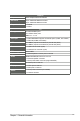
3.3 Advanced menu............................................................................ 3-4 3.3.1 3.3.2 CPU Configuration........................................................... 3-5 3.3.4 System Agent Configuration............................................ 3-7 3.3.3 3.3.5 3.3.6 3.3.7 3.3.8 3.3.9 3.4 3.3.10 3.4.1 AMT Configuration........................................................... 3-8 USB Configuration...........................................................
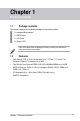
Chapter 1 Product overview 1.1 Package contents Check your industrial motherboard package for the following items. 1 x Industrial Motherboard 1 x SATA Cable 1 x I/O Shield 1 x Support CD If any of the above items is damaged or missing, contact your distributor or sales representative immediately. 1.
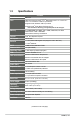
1.3 Specifications Form factor CPU SYSTEM Mini-ITX LGA1155 socket for Intel® 3nd/2nd Generation Core™ i7 / Core™ i5 / Core™ i3 / Pentium® / Celeron® processors Supports Intel® 22/32nm CPU up to 95W Supports Intel® Turbo Boost Technology 2.0* Memory Chipset I/O Chipset Ethernet BIOS Wake on LAN Watchdog Timer TPM H/W Status Monitor Smart Fan Control Power State Expansion slot Battery *Intel® Turbo Boost Technology 2.0 support depends on the CPU types. 2 x DIMM (8GB per DIMM), max.
DISPLAY Chipset Resolution Intel® Graphics Media Accelerator Output interface 1 x DVI-D Storage Serial port USB Fan RTC Keyboard/Mouse Audio Ethernet Up to 1920x1200@60Hz for DVI-D Up to 1920x1200@60Hz for DVI-I 1 x DVI-I I/O 2 x SATA 6.0Gb/s ports 2 x SATA 3.0Gb/s ports RAID 0 / 1 / 5 / 10 1 x RS-232/422/485 supports 5V/12V/RI option (COM1, box header) 1 x RS-232 (COM2, box header) 4 x USB3.0 (2 ports at mid-board, 2 ports at rear panel) 8 x USB2.
1-4 EMB-Q77A
Chapter 2 Motherboard information 2.1 Before you proceed Take note of the following precautions before you install motherboard components or change any motherboard settings. CAUTION! • Unplug the power cord from the wall socket before touching any component. • Before handling components, use a grounded wrist strap or touch a safely grounded object or a metal object, such as the power supply case, to avoid damaging them due to static electricity.
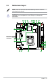
2.2 Motherboard layout NOTE: Place four screws into the holes indicated by circles to secure the motherboard to the chassis. CAUTION! Do not overtighten the screws! Doing so can damage the motherboard. 1 2 3 4 5 6 7 8 17.0cm(6.7in) COM1 LAN1_USB3_12 17.0cm(6.
Connectors/Jumpers/Slots 1. CPU and system fan connectors (4-pin CPU_FAN, 4-pin CHA_FAN) 2. USB 3.0 connector (20-1 pin USB3_34) 3. Serial ATA 3.0Gb/s connectors (7-pin SATA3G_1, SATA3G_2) 4. USB 2.0 connector (10-1 pin USB1112) 5. Clear RTC RAM (CLRTC) Page 2-20 2-24 2-23 2-24 2-13 6. 7. 8. 9. 10. Chassis intrusion connector (4-1 pin CHASSIS) Serial port connectors (10-1 pin COM1, 10-1 COM2) DIMM memory slots ATX power connectors (24-pin EATXPWR, 4-pin EATX12V) 2-21 2-25 2-11 2-19 2-14 15. 16. 17. 18.
2.3 2.3.
2.3.
2.4 Central Processing Unit (CPU) The motherboard comes with a surface mount LGA1155 socket designed for the Intel® 3rd/2nd Generation Core™ i7 / Core™ i5 / Core™ i3 / Pentium® / Celeron® processors. EMB-Q77A CPU socket LGA1155 IMPORTANT: Unplug all power cables before installing the CPU. CAUTION! 2-6 • Upon purchase of the motherboard, ensure that the PnP cap is on the socket and the socket contacts are not bent.
2.4.1 Installing the CPU CAUTION! The LGA1156 CPU is incompatible with the LGA1155 socket. DO NOT install a LGA1156 CPU on the LGA1155 socket.
4 C A B 5 2-8 EMB-Q77A
2.4.2 CPU heatsink and fan assembly installation CAUTION! Apply the Thermal Interface Material to the CPU heatsink and CPU before you install the heatsink and fan if necessary.
To uninstall the CPU heatsink and fan assembly 1 2 A B B A 2-10 EMB-Q77A
2.5 System memory This motherboard comes with two Double Data Rate 3 (DDR3) Dual Inline Memory Module (DIMM) sockets. A DDR3 module has the same physical dimensions as a DDR2 DIMM but is notched differently to prevent installation on a DDR2 DIMM socket. DDR3 modules are developed for better performance with less power consumption.
2.5.
2.6 1. Jumpers Clear RTC RAM (CLRTC) This jumper allows you to clear the Real Time Clock (RTC) RAM in CMOS. You can clear the CMOS memory of system setup parameters by erasing the CMOS RTC RAM data. The onboard button cell battery powers the RAM data in CMOS, which include system setup information such as system passwords. 1 2 CLRTC RTC Batt. (Default) 2 3 Clear CMOS EMB-Q77A Clear RTC RAM To erase the RTC RAM: 1. Turn OFF the computer and unplug the power cord. 2.
2. Intel® ME Jumper (3-pin DIS_ME) This jumper allows you to force Intel® Management Engine (ME) boot from recovery mode when ME become corrupted. 1 2 2 3 DIS_ME ME Enable (Default) ME Disable EMB-Q77A Intel® ME jumper 3.
2.7 1. Onboard LEDs Standby Power LED The motherboard comes with a standby power LED that lights up to indicate that the system is ON, in sleep mode, or in soft-off mode. This is a reminder that you should shut down the system and unplug the power cable before removing or plugging in any motherboard component. The illustration below shows the location of the onboard LED.
2.9 2.9.1 Connectors Rear panel connectors 1 11 1. 2. 3. 4. 2 10 3 9 5 6 4 8 7 PS/2 keyboard/mouse port (purple/green). This port is for a PS/2 keyboard or mouse. DVI-D port. This port is for any DVI-D compatible device. DVI-D can’t be converted to output RGB signal to CRT and isn’t compatible with DVI-I. USB 2.0 ports. These four 4-pin Universal Serial Bus (USB) ports are available for connecting USB 2.0/1.1 devices. LAN1 (RJ-45) port.
5. 6. 7. Line In port (light blue). This port connects the tape, CD, DVD player, or other audio sources. Line Out port (lime). This port connects to a headphone or a speaker. In a 4-channel, 6-channel and 8-channel configurations, the function of this port becomes Front Speaker Out. Microphone port (pink). This port connects a microphone. NOTE: Refer to the audio configuration table below for the function of the audio ports in the 2, 4, 6 or 8-channel configuration.
10. LAN2 (RJ-45) port. These ports allow Gigabit connection to a Local Area Network (LAN) through a network hub. Refer to the table below for the LAN2 port LED indications. LAN2 port LED indications ACT/LINK LED Status Description OFF No link GREEN Linked BLINKING Data activity 11. 2-18 SPEED LED Status Description OFF 10 Mbps connection ORANGE 100 Mbps connection GREEN 1 Gbps connection Activity Link LED Speed LED LAN port USB 2.0 ports.
2.9.2 1. Internal connectors ATX power connectors (24-pin EATXPWR, 4-pin EATX12V) These connectors are for ATX power supply plugs. The power supply plugs are designed to fit these connectors in only one orientation. Find the proper orientation and push down firmly until the connectors completely fit. COM COM EATX12V +12V DC +12V DC PIN 1 EATXPWR +3.3VDC +12 VDC +12 VDC +5VSB PWR_OK COM +5 VDC COM +5 VDC COM +3.3VDC +3.3VDC COM +5VDC +5VDC +5VDC -5VDC COM COM COM PS_ON# COM -12VDC +3.
2. CPU and chassis fan connectors (4-pin CPU_FAN, 4-pin CHA_FAN) Connect the fan cables to the fan connectors on the motherboard, ensuring that the black wire of each cable matches the ground pin of the connector. CPU_FAN CHA_FAN GND VCC SENSE PWM GND VCC SENSE PWM EMB-Q77A CPU fan connector CAUTION: Do not forget to connect the fan cables to the fan connectors. Insufficient air flow inside the system may damage the motherboard components.
Front panel audio connector (10-1 pin AAFP) NC AGND NC NC SENSE2_RETUR This connector is for a chassis-mounted front panel audio I/O module that supports either HD Audio or legacy AC`97 audio standard. Connect one end of the front panel audio I/O module cable to this connector. AGND NC SENSE1_RETUR 3.
System panel connector (10-1 pin F_PANEL) This connector supports several chassis-mounted functions. (NC) HWRST# GND HDD_LEDHDD_LED+ GND PANSWH# PLEDPLED+ PIN 1 RESET F_PANEL +HDD_LED +PWR_LED PWR_BTN 5. EMB-Q77A System panel connector • • • • 2-22 System power LED (2-pin PWR_LED) This 2-pin connector is for the system power LED. Connect the chassis power LED cable to this connector.
6. Serial ATA 3.0Gb/s connectors (7-pin SATA3G_1, SATA3G_2) These connectors connect to Serial ATA 3.0 Gb/s hard disk drives and optical drives via Serial ATA 3.0 Gb/s signal cables. SATA3G_1 GND RSATA_RXP1 RSATA_RXN1 GND RSATA_TXN1 RSATA_TXP1 GND SATA3G_2 GND RSATA_RXP2 RSATA_RXN2 GND RSATA_TXN2 RSATA_TXP2 GND EMB-Q77A SATA 3.0Gb/s connectors NOTES: 7. • You must install Windows® XP Service Pack 3 or later version before using Serial ATA hard disk drives.
8. USB 3.0 connector (20-1 pin USB3_34) These connectors allow you to connect a USB 3.0 module for additional USB 3.0 front panel ports. With an installed USB 3.0 module, you can enjoy all the benefits of USB 3.0 including faster data transfer speeds of up to 5Gbps, faster charging time for USB-chargeable devices, optimized power efficiency, and backward compatibility with USB 2.0.
9. USB 2.0 connector (10-1 pin USB1112) This connector is for USB 2.0 ports. Connect the USB module cable to connector USB1112. This USB connector complies with USB 2.0 specification that supports up to 480 Mbps connection speed. +5V_USB_P1112 S_USB_PN11 S_USB_PP11 GND NC USB1112 +5V_USB_P1112 S_USB_PN10 S_USB_PP10 GND PIN 1 EMB-Q77A USB2.0 connector Never connect a 1394 cable to the USB connector. Doing so will damage the motherboard. The USB module cable is purchased separately.
10. Serial port connectors (10-1 pin COM1, COM2) These connectors are for serial (COM) ports. Connect the serial port module cables to these connectors, then install the module to a slot opening at the back of the system chassis.
11. Speaker connector (4-pin SPEAKER) The 4-pin connector is for the chassis-mounted system warning speaker. The speaker allows you to hear system beeps and warnings. SPEAKER PIN 1 +5V GND GND Speaker Out EMB-Q77A Speaker Out Connector 12. Minicard connector Use this connector to connect a Minicard reader. MINICARD EMB-Q77A MINICARD connector 13.
2-28 EMB-Q77A
Chapter 3 BIOS setup 3.1 BIOS setup program Use the BIOS Setup program to update the BIOS or configure its parameters. The BIOS screens include navigation keys and brief online help to guide you in using the BIOS Setup program. Entering BIOS Setup at startup To enter BIOS Setup at startup: Press during the Power-On Self Test (POST). If you do not press , POST continues with its routine.
3.1.1 BIOS menu screen 3.1.2 Menu bar The menu bar on top of the screen has the following main items: Main Advanced Monitor Boot For changing the basic system configuration. For changing the advanced system settings. For viewing and changing fan and voltage information. For changing the system boot configuration. Tool For updating the BIOS and viewing DRAM SPD Information. Exit For selecting the exit options and loading default settings.
3.2 Main menu The Main menu provides you an overview of the basic system information, and allows you to set the system date, time, language, and security settings. 3.2.1 System Language [English] System language default is set to English. 3.2.2 System Date [Day MM/DD/YYYY] Allows you to set the system date. 3.2.3 System Time [HH:MM:SS] Allows you to set the system time. 3.2.4 Security The Security menu items allow you to change the system security settings.
3.3 Advanced menu The Advanced menu items allow you to change the settings for the CPU and other system devices. Be cautious when changing the settings of the Advanced menu items. Incorrect field values can cause the system to malfunction. 3.3.1 Trusted Computing This item appears only when a TPM module is connected to the motherboard and allows you to change TPM settings. TPM Support [Enabled] Allows you to enable or disable TPM support.
3.3.2 CPU Configuration The items in this menu show the CPU-related information that the BIOS automatically detects. The items shown in the submenu may be different due to the CPU installed. Active Processor Cores [All] Allows you to choose the number of CPU cores to activate in each processor package. Configuration options: [All] [1] [2] [3] Configuration options for active processor cores are dependent on the installed CPU.
3.3.3 SATA Configuration While entering Setup, the BIOS automatically detects the presence of SATA devices. The SATA Port items show Not Present if no SATA device is installed to the corresponding SATA port. SATA Mode Selection [AHCI] Allows you to set the SATA configuration. [Disabled] Disables the SATA function. [IDE] Set to [IDE] when you want to use the Serial ATA hard disk drives as Parallel ATA physical storage devices.
3.3.4 System Agent Configuration VT-d [Disabled] Allows you to enable virtualization technology function on memory control hub. [Enabled] Enables the function. [Disabled] Disables this function. Graphics Configuration Primary Display [Auto] Allows you to decide which graphics controller to use as the primary boot device. Configuration options: [Auto] [iGPU] [PCIE] iGPU Memory [Auto] Allows you to select the amount of system memory allocated to DVMT 5.0 used by the iGPU.
3.3.5 Intel TXT(LT) Configuration Allows you to enable/disable Intel Trusted Execution Technology support. Secure Mode Extensions (SMX) [Enabled] [Disabled] Enables Secure Mode Extensions. Disables Secure Mode Extensions. [Enabled] Enables support for Intel Trusted Execution Technology. Disables support for Intel Trusted Execution Technology. Intel TXT(LT) Support [Disabled] To enable Intel TXT(LT) Support, SMX and VT-d items should also be enabled. 3.3.
3.3.7 USB Configuration The items in this menu allow you to change the USB-related features. The USB Devices item shows the auto-detected values. If no USB device is detected, the item shows None. Intel USB2.0 EHCI Controller [Enabled] [Enabled] [Disabled] Enables USB2.0 EHCI Controller. Disables USB2.0 EHCI Controller. Legacy USB Support [Enabled] [Enabled] [Disabled] [Auto] Enables the support for USB devices on legacy operating systems (OS).
3.3.8 Onboard Devices Configuration HD Audio Controller [Enabled] [Enabled] [Disabled] Enables the High Definition Audio Controller. Disables the controller. The following two items appear only when you set the HD Audio Controller item to [Enabled]. Front Panel Type [HD] Allows you to set the front panel audio connector (AAFP) mode to legacy AC’97 or high-definition audio depending on the audio standard that the front panel audio module supports.
Serial Port1~2 (COM1~COM2) Configuration The sub-items in this menu allow you to set the serial port configuration. Serial Port [Enabled] Allows you to enable or disable the serial port (COM). Configuration options: [Enabled] [Disabled] RS Mode [RS232] Allows you to select COM RS Mode. Configuration options: [RS232] [RS422] [RS485] Change Settings [IO=3F8h; IRQ=4] Allows you to select the Serial Port base address.
3.3.9 APM AT/ATX Power Type [ATX Mode] Select AT or ATX Power Type. Configuration options: [AT Mode] [ATX Mode] Intel vPro Preparation Requirements [Unsupported] Enable/disable support for Intel vPro. Configuration options: [Unsupported] [Supported] Restore AC Power Loss [Power Off] [Power On] [Power Off] [Last State] The system goes into on state after an AC power loss. The system goes into off state after an AC power loss.
3.3.10 Network Stack Network Stack [Disabled] This item allows user to disable or enable the UEFI network stack. Configuration options: [Disabled] [Enabled] The following two items appear only when you set the previous item to [Enabled]. Ipv4 PXE Support [Enabled] This item allows user to disable or enable the Ipv4 PXE Boot support. Configuration options: [Disable Link] [Enable] Ipv6 PXE Support [Enabled] This item allows user to disable or enable the Ipv6 PXE Boot support.
3.4 Monitor menu The Monitor menu displays the system temperature/power status, and allows you to change the fan settings. 3.4.1 CPU Temperature / MB Temperature [xxxºC/xxxºF] The onboard hardware monitor automatically detects and displays the CPU and motherboard temperatures. Select Ignore if you do not wish to display the detected temperatures. 3.4.
3.4.3 CPU Q-Fan Control [Enabled] [Disabled] [Enabled] Disables the CPU Q-Fan control feature. Enables the CPU Q-Fan control feature. CPU Fan Speed Low Limit [200 RPM] This item appears only when you enable the CPU Q-Fan Control feature and allows you to disable or set the CPU fan warning speed.
Chassis Q-Fan Control [Enabled] [Disabled] [Enabled] Disables the Chassis Q-Fan control feature. Enables the Chassis Q-Fan control feature. Chassis Fan Speed Low Limit [600 RPM] This item appears only when you enable the Chassis Q-Fan Control feature and allows you to disable or set the chassis fan warning speed.
CPU Fan Min. Duty Cycle(%) [60] Use the <+> and <-> keys to adjust the minimum chassis fan duty cycle. The values range from 60% to 100%. When the chassis temperature is under 40ºC, the chassis fan will operate at the minimum duty cycle. 3.4.4 CPU Voltage, 3.3V Voltage, 5V Voltage, 12V Voltage The onboard hardware monitor automatically detects the voltage output through the onboard voltage regulators. Select Ignore if you do not want to detect this item.
3.5 Boot menu The Boot menu items allow you to change the system boot options. 3.5.1 Fast Boot [Enabled] Enable or disable boot with initialization of a minimal set of devices to launch active boot option. Configuration options: [Disabled] [Enabled] The following three items appear only when you set Fast Boot to [Enabled]. USB Support [Partial Initial] [Disabled] [Full Initial] [Partial Initial] 3-18 All USB devices will not be available until after OS boot.
PS/2 Keyboard and Mouse Support [Auto] [Auto] [Disabled] [Full Initialization] Automatic configuration. Disables PS/2 keyboard and mouse support during POST. PS/2 keyboard and mouse support are enabled during POST. Network Stack Driver Support [Disabled] [Disabled] The BIOS skips over the Network Stack Driver and tries to boot from the next device. Allows the BIOS to boot from the Network Stack Driver. [Enabled] 3.5.2 Bootup NumLock State [On] [On] [Off] 3.5.
3.5.6 CSM (Compatibility Support Module) This option controls whether or not CSM will be launched. Launch CSM [Enabled] Configuration option: [Auto] [Enabled] [Disabled] The following four items appear only when you set Launch CSM to [Enabled].
Save Secure Boot keys Platform Key (PK) Management Delete PK Configuration options: [Yes] [No] Load PK from File Key Exchange Key (KEK) Management Delete the KEK Configuration options: [Yes] [No] Load KEK from File Append KEK from File Database (DB) Management Delete the DB Configuration options: [Yes] [No] Load DB from File Append DB from File DBX Management Delete the DBX Configuration options: [Yes] [No] Load DBX from File Append DBX from File Chapter 3: BIOS setup 3-21
3.5.8 Boot Option Priorities These items specify the boot device priority sequence from the available devices. The number of device items that appears on the screen depends on the number of devices installed in the system. • To select the boot device during system startup, press when ASUS Logo appears. • To access Windows OS in Safe Mode, do any of the following: - 3.5.9 Press when ASUS Logo appears. Press after POST. Boot Override These items displays the available devices.
3.6 Tools menu The Tools menu items allow you to configure options for special functions. Select an item then press to display the submenu. 3.6.1 EZ Flash 2 Utility Allows you to run EZ Flash 2. Press [Enter] to launch the EZ Flash 2 screen. 3.6.2 DRAM SPD Information DIMM Slot # [DIMM_A1] Displays the Serial Presence Detect (SPD) information of the DIMM module installed on the selected slot.
3.7 Exit menu The Exit menu items allow you to load the optimal default values for the BIOS items, and save or discard your changes to the BIOS items. You can access the EZ Mode from the Exit menu. Load Optimized Defaults This option allows you to load the default values for each of the parameters on the Setup menus. When you select this option or if you press , a confirmation window appears. Select Yes to load the default values.
Appendix Notices Federal Communications Commission Statement This device complies with Part 15 of the FCC Rules. Operation is subject to the following two conditions: • This device may not cause harmful interference. • This device must accept any interference received including interference that may cause undesired operation. This equipment has been tested and found to comply with the limits for a Class A digital device, pursuant to Part 15 of the FCC Rules.
電子信息產品污染控制標示:圖中之數字為產品之環保使用期限。僅指電子 信息產品中含有的有毒有害物質或元素不致發生外洩或突變從而對環境造成 污染或對人身、財產造成嚴重損害的期限。 有毒有害物質或元素的名稱及含量說明標示: 有害物質或元素 部件名稱 鉛 (Pb) 汞 (Hg) 鎘 (Cd) 六 價 (Cr(VI)) 印刷電路板及其 電子組件 × ○ ○ 外部信號連接頭 及線材 × ○ ○ 鉻 多 溴 聯 苯 (PBB) 多溴二苯醚 (PBDE) ○ ○ ○ ○ ○ ○ ○: 表示該有毒有害物質在該部件所有均質材料中的含量均在 SJ/T 113632006 標准規定的限量要求以下。 ×: 表示該有毒有害物質至少在該部件的某一均質材料中的含量超出 SJ/T 11363-2006 標准規定的限量要求,然該部件仍符合歐盟指令 2002/95/ EC 的規范。 備註:此產品所標示之環保使用期限,係指在一般正常使用狀況下。 A-2 EMB-Q77A