Industrial Motherboard EMB-Q77B
E8890 First Edition January 2014 Copyright Notice This document is copyrighted, 2014. All rights are reserved. The original manufacturer reserves the right to make improvements to the products described in this manual at any time without notice. No part of this manual may be reproduced, copied, translated, or transmitted in any form or by any means without the prior written permission of the original manufacturer. Information provided in this manual is intended to be accurate and reliable.
Contents Chapter 1: Product overview 1.1 Package contents.......................................................................... 1-1 1.3 Specifications................................................................................ 1-2 1.2 Features......................................................................................... 1-1 Chapter 2: Motherboard information 2.1 Before you proceed...................................................................... 2-1 2.3 Screw size.......
3.3.6 CPU Configuration........................................................... 3-5 3.3.8 Intel TXT(LT) Configuration.............................................. 3-6 3.3.7 3.3.9 3.3.10 3.3.11 3.3.12 3.4 3.3.13 3.6 3.7 AMT Configuration........................................................... 3-7 USB Configuration........................................................... 3-7 NCT6779D Super IO Configuration................................. 3-8 NCT6779D H/W Monitor............................
Chapter 1 Product overview 1.1 Package contents Check your industrial motherboard package for the following items. 1 x Industrial Motherboard 1 x SATA Cable 1 x I/O Shield 1 x Support CD If any of the above items is damaged or missing, contact your distributor or sales representative immediately. 1.
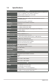
1.3 Specifications CPU Chipset Memory Graphics I/O Chipset Storage Ethernet Audio TPM Expansion slots BIOS H/W Status Monitor Smart Fan Control Watchdog Timer Wake on LAN/PXE Power State SYSTEM LGA1155 socket for Intel® 3nd/2nd Generation Core™ i7 / Core™ i5 / Core™ i3, Pentium®, and Celeron® processors Supports Intel® 22/32nm CPU up to 95W Intel® Q77 Express Chipset 2 x DIMMs, max. 16GB, DDR3 1600/1333/1066 Mhz non-ECC.
I/O Display 1 x HDMI port Audio LAN Serial Port 3 Audio jack (Line-in, Mic-in, Line-out) PS/2 Port FAN 1 x VGA port 2 x LAN (RJ-45) ports 1 x RS-232/422/485 supports 5V/12V/RI option (COM1, D-Sub 9) 1 x RS-232 (COM2, D-Sub 9) 1 x PS/2 Keyboard port 1 x PS/2 Mouse port 1 x 4-pin CPU Fan connector 1 x 4-pin Chassis Fan connector ENVIRONMENT & POWER & ME Battery Lithium battery Power Requirement 1 x 24-pin ATX connector Power Compliance Operating Temperature Operating Humidity 1 x 4-pin ATX 12V
Rear panel ports PLACEMENT 31 x PS/2 Keyboard port 1 x PS/2 Mouse port 1 x HDMI port 1 x VGA port 2 x LAN (RJ-45) ports 2 x COM ports 4 x USB 3.0 ports 3 x Audio jacks Internal connectors/ 2 x USB 2.0 connectors support additional 4 USB 2.
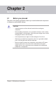
Chapter 2 Motherboard information 2.1 Before you proceed Take note of the following precautions before you install motherboard components or change any motherboard settings. CAUTION! • Unplug the power cord from the wall socket before touching any component. • Before handling components, use a grounded wrist strap or touch a safely grounded object or a metal object, such as the power supply case, to avoid damaging them due to static electricity.
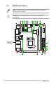
2.2 Motherboard layout NOTE: Place four screws into the holes indicated by circles to secure the motherboard to the chassis. CAUTION! Do not overtighten the screws! Doing so can damage the motherboard. 1 2 3 4 5 4 6 7 8 9 17.0cm(6.7in) CLRTC USB56 CHASSIS USB1112 Intel® BATTERY CHA_FAN CPU_FAN COM1 _VSET KBMS_USB910 LAN2_USB3_34 10 EATXPWR LGA1155 Place this side towards the rear of the chassis 17.0cm(6.
Connectors/Jumpers/Slots 1. Serial ATA 6.0Gb/s connectors (7-pin SATA6G_1, SATA6G_2) 2. CPU and chassis fan connectors (4-pin CPU_FAN, 4-pin CHA_FAN) 3. COM1 Ring/+5V/+12V selection (COM1_VSET) 4. USB 2.0 connector (10-1 pin USB56, USB1112) 5. Serial ATA 3.0Gb/s connectors (7-pin SATA3G_1, SATA3G_2) Page 2-21 2-19 2-14 2-22 6. 7. 8. 9. 10. 11. 12. 13. 14. 15.
2.3 2.3.
2.3.
2.4 Central Processing Unit (CPU) The motherboard comes with a surface mount LGA1155 socket designed for the Intel® 3rd/2nd Generation Core™ i7 / Core™ i5 / Core™ i3 / Pentium® / Celeron® processors. EMB-Q77B CPU socket LGA1155 IMPORTANT: Unplug all power cables before installing the CPU. CAUTION! 2-6 • Upon purchase of the motherboard, ensure that the PnP cap is on the socket and the socket contacts are not bent.
2.4.1 Installing the CPU CAUTION! The LGA1156 CPU is incompatible with the LGA1155 socket. DO NOT install a LGA1156 CPU on the LGA1155 socket.
4 C A B 5 2-8 EMB-Q77B
2.4.2 CPU heatsink and fan assembly installation CAUTION! Apply the Thermal Interface Material to the CPU heatsink and CPU before you install the heatsink and fan if necessary.
To uninstall the CPU heatsink and fan assembly 1 2 A B B A 2-10 EMB-Q77B
2.5 System memory This motherboard comes with two Double Data Rate 3 (DDR3) Dual Inline Memory Module (DIMM) sockets. A DDR3 module has the same physical dimensions as a DDR2 DIMM but is notched differently to prevent installation on a DDR2 DIMM socket. DDR3 modules are developed for better performance with less power consumption.
2.5.
2.6 1. Jumpers Clear RTC RAM (CLRTC) This jumper allows you to clear the Real Time Clock (RTC) RAM in CMOS. You can clear the CMOS memory of system setup parameters by erasing the CMOS RTC RAM data. The onboard button cell battery powers the RAM data in CMOS, which include system setup information such as system passwords. 1 2 CLRTC Normal (Default) 2 3 Clear RTC1 EMB-Q77B Clear RTC RAM To erase the RTC RAM: 1. Turn OFF the computer and unplug the power cord. 2.
2. Intel® ME Jumper (3-pin DIS_ME) This jumper allows you to force Intel® Management Engine (ME) boot from recovery mode when ME become corrupted. 1 2 2 3 DIS_ME ME Enable (Default) ME Disable EMB-Q77B Intel® ME jumper 3.
2.7 1. Onboard LEDs Standby Power LED The motherboard comes with a standby power LED that lights up to indicate that the system is ON, in sleep mode, or in soft-off mode. This is a reminder that you should shut down the system and unplug the power cable before removing or plugging in any motherboard component. The illustration below shows the location of the onboard LED.
2.9 Connectors 2.9.1 1. 2. Rear panel connectors 1 2 3 11 10 9 4. 8 7 PS/2 mouse port (green). This port is for a PS/2 mouse. COM1 (Serial) port. This port allow you to connect devices that have serial connectors such as mouse, modem, or printers. This port supports RS-232, RS-422, and RS-485 serial specifications. PIN 1 3 5 7 9 3. 5 6 4 SIGNAL DCD (422TXD-/485DATA-) TXD (422TXD+/485DATA+) GND RTS RI/+12V/+5V PIN 2 4 6 8 10 SIGNAL RXD (422RXD+) DTR (422RXD-) DSR CTS N.C.
5. 6. 7. Line In port (light blue). This port connects the tape, CD, DVD player, or other audio sources. Line Out port (lime). This port connects to a headphone or a speaker. In a 4-channel, 6-channel and 8-channel configurations, the function of this port becomes Front Speaker Out. Microphone port (pink). This port connects a microphone. NOTE: Refer to the audio configuration table below for the function of the audio ports in the 2.1, 4.1, 5.1, or 7.1-channel configuration. Audio 2.1, 4.1, 5.1, or 7.
9. HDMI port. This port is for a High-Definition Multimedia Interface (HDMI) connector, and is HDCP compliant allowing playback of HD DVD, Blu-Ray, and other protected content. 10. COM2 (Serial) port. This port allow you to connect devices that have serial connectors such as mouse, modem, or printers. This port supports RS-232 serial specification. 11. PS/2 Keyboard port (purple). This port connects to a PS/2 keyboard. 2.9.2 1.
2. CPU and chassis fan connectors (4-pin CPU_FAN, 4-pin CHA_FAN) Connect the fan cables to the fan connectors on the motherboard, ensuring that the black wire of each cable matches the ground pin of the connector. CPU_FAN GND VCC SENSE PWM EMB-Q77B CPU fan connector CAUTION: Do not forget to connect the fan cables to the fan connectors. Insufficient air flow inside the system may damage the motherboard components.
4. System panel connector (10-1 pin F_PANEL) This connector supports several chassis-mounted functions. (NC) HWRST# Ground HDD_LEDHDD_LED+ PIN 1 RESET GND PWR PWR_LEDPWR_LED+ +HDD_LED +PWR LED PWR BTN F_PANEL EMB-Q77B System panel connector • • • System power LED (2-pin PWR_LED) This 2-pin connector is for the system power LED. Connect the chassis power LED cable to this connector. The system power LED lights up when you turn on the system power, and blinks when the system is in sleep mode.
6. Serial ATA 3.0Gb/s connectors (7-pin SATA3G_1, SATA3G_2) These connectors connect to Serial ATA 3.0 Gb/s hard disk drives and optical drives via Serial ATA 3.0 Gb/s signal cables. SATA3G_1 GND RSATA_RXP1 RSATA_RXN1 GND RSATA_TXN1 RSATA_TXP1 GND SATA3G_2 GND RSATA_RXP2 RSATA_RXN2 GND RSATA_TXN2 RSATA_TXP2 GND EMB-Q77B SATA 3.0Gb/s connectors NOTES: 7. • You must install Windows® XP Service Pack 3 or later version before using Serial ATA hard disk drives.
8. USB 2.0 connectors (10-1 pin USB56, USB1112) This connector is for USB 2.0 ports. Connect the USB module cable to connector USB1112. This USB connector complies with USB 2.0 specification that supports up to 480 Mbps connection speed. USB1112 +5V USB5USB5+ GND (NC) +5V USB11USB11+ GND (NC) USB56 +5V USB12USB12+ GND PIN 1 +5V USB6USB6+ GND PIN 1 EMB-Q77B USB2.0 connector Never connect a 1394 cable to the USB connector. Doing so will damage the motherboard.
Chapter 3 BIOS setup 3.1 BIOS setup program Use the BIOS Setup program to update the BIOS or configure its parameters. The BIOS screens include navigation keys and brief online help to guide you in using the BIOS Setup program. Entering BIOS Setup at startup To enter BIOS Setup at startup: Press during the Power-On Self Test (POST). If you do not press , POST continues with its routine.
3.1.1 BIOS menu screen Menu items Main Menu bar Configuration fields General help Aptio Setup Utility - Copyright (C) 2011 American Megatrends, Inc. Advanced Chipset Boot Security Save & Exit BIOS Information R0.5(EQ77BM05) (12/10/2013 BIOS Vendor Core Version Compliancy Set the Date. Use Tab to switch between Date elements. American Megatrends 4.6.5.4 UEFI 2.3.1; PI 1.
3.2 Main menu When you enter the BIOS Setup program, the Main menu screen appears, giving you an overview of the basic system information. Refer to section 3.1.1 BIOS menu screen for information on the menu screen items and how to navigate through them. Main Aptio Setup Utility - Copyright (C) 2012 American Megatrends, Inc. Advanced Chipset Boot Security Save & Exit BIOS Information R0.5 (EQ77BM05) (12/10/2013) BIOS Vendor Core Version Compliancy Set the Date. Use Tab to switch between Date elements.
3.3 Advanced menu The Advanced menu items allow you to change the settings for the CPU and other system devices. Be cautious when changing the settings of the Advanced menu items. Incorrect field values can cause the system to malfunction. Main Aptio Setup Utility - Copyright (C) 2012 American Megatrends, Inc.
3.3.4 S5 RTC Wake Settings This item allows you to enable the system to wake up from S5 state using an alert event. Wake system with Fixed Time [Disabled] Allows you to enable or disable the system’s wake-on alert event. When enabled, the system wakes up on the specified time. Configuration options: [Enabled] [Disabled] Wake system with Dynamic Time [Disabled] Allows you to enable or disable the system’s wake-on alert event.
Intel(R) Virtualization Tech [Enabled] Enables or disables Intel® Virtualization Technology. Virtualization enhanced by Intel® Virtualization Technology allows a platform to run multiple operating systems and applications in independent partitions. With virtualization, one computer system can function as multiple virtual systems. Configuration options: [Enabled] [Disabled] 3.3.7 SATA Configuration While entering Setup, the BIOS automatically detects the presence of SATA devices.
3.3.9 AMT Configuration The items in this menu allow you to change the Intel® Active Management Technology (AMT) feature. Intel® AMT [Enabled] Allow you to enable or disable the Intel® Active Management Technology (AMT) in the BIOS extension. Configuration options: [Enabled] [Disabled] • iAMT H/W is always enabled. This option just controls the BIOS extension execution. If enabled, this requires additional firmware in the SPI device.
3.3.11 NCT6779D Super IO Configuration The items in this menu allow you to configure the system super IO chip settings. Serial Port 1/Port 2 Configuration Allow you to configure the Serial Port 1/Port 2 settings. Serial Port [Enabled] Enables or disables the Serial COM port. Configuration options: [Enabled] [Disabled] Change Settings [Auto] Allows you to select an optimal setting for the Super IO device.
3.4 Chipset The Chipset menu allows you to change the advanced chipset settings. Select an item then press to display the sub-menu. 3.4.1 Power Mode [ATX Type] Allows you to select the power supply type. Configuration options: [ATX Type] [AT Type] 3.4.2 PCH-IO Configuration PCIE Express Configuration Allows you to configure the PCI Express settings. PCH Azalia Configuration Allows you to configure the PCH Azalia settings.
Internal Graphics [Enabled] Allows you to keep the IGD enabled based on the setup options. Configuration options: [Auto] [Enabled] [Disabled] DVMT Pre-Allocated [64M] Allows you to select the DVMT 5.0 Pre-Allocated (Fixed) graphics memory size used by the integrated graphics device. Configuration options: [32M] [64M] [96M] [128M] [160M] [192M] [224M] [256M] [288M] [320M] [352M] [384M] [416M] [448M] [480M] [512M] [1024M] DVMT Total Gfx Mem [MAX] Allows you to select the DVMT 5.
3.6 Security menu The Security menu items allow you to change the system security settings. Administrator Password If you have set an administrator password, we recommend that you enter the administrator password for accessing the system. Otherwise, you might be able to see or change only selected fields in the BIOS setup program. To set an administrator password: 1. Select the Administrator Password item and press . 2. From the Create New Password box, key in a password, then press .
4. Confirm the password when prompted. To clear the user password, follow the same steps as in changing a user password, but press when prompted to create/confirm the password. After you clear the password, the User Password item on top of the screen shows Not Installed. 3.7 Save & Exit menu The Save & Exit menu items allow you to load the optimal default values for the BIOS items, and save or discard your changes to the BIOS items.
Appendix Notices Federal Communications Commission Statement This device complies with Part 15 of the FCC Rules. Operation is subject to the following two conditions: • This device may not cause harmful interference. • This device must accept any interference received including interference that may cause undesired operation. This equipment has been tested and found to comply with the limits for a Class A digital device, pursuant to Part 15 of the FCC Rules.
電子信息產品污染控制標示:圖中之數字為產品之環保使用期限。僅指電子 信息產品中含有的有毒有害物質或元素不致發生外洩或突變從而對環境造成 污染或對人身、財產造成嚴重損害的期限。 有毒有害物質或元素的名稱及含量說明標示: 有害物質或元素 部件名稱 鉛� ���� (Pb) 汞� ���� (Hg) 鎘� ���� (Cd) 六 價 (Cr(VI)) 印刷電路板及其 電子組件 × ○ ○ 外部信號連接頭 及線材 × ○ ○ 鉻� 多 溴 聯 苯� (PBB) 多溴二苯醚 (PBDE) ○ ○ ○ ○ ○ ○ ○: 表示該有毒有害物質在該部件所有均質材料中的含量均在 SJ/T 113632006 標准規定的限量要求以下。 ×: 表示該有毒有害物質至少在該部件的某一均質材料中的含量超出 SJ/T 11363-2006 標准規定的限量要求,然該部件仍符合歐盟指令 2002/95/ EC 的規范。 備註:此產品所標示之環保使用期限,係指在一般正常使用狀況下。 A-2 EMB-Q77B