EPIC Board EPIC-9457 Rev.A EPIC-9457 Rev.A ® Intel Atom™ N270 Processor DDR2 400/533 Memory Up to 24-bit Dual-channel LVDS LCD 6 USB 2.0 / 4 COMs / 1 EIDE/ 2 SATAII/ 1 CompactFlash/ 1 Digital I/O EPIC-9457 Manual Rev.A 3rd Ed.
EPIC Board EPIC-9457 Rev.A Copyright Notice This document is copyrighted, 2010. All rights are reserved. The original manufacturer reserves the right to make improvements to the products described in this manual at any time without notice. No part of this manual may be reproduced, copied, translated, or transmitted in any form or by any means without the prior written permission of the original manufacturer. Information provided in this manual is intended to be accurate and reliable.
EPIC Board EPIC-9457 Rev.A Acknowledgments All other products’ name or trademarks are properties of their respective owners. z Award is a trademark of Award Software International, Inc. z CompactFlash™ is a trademark of the Compact Flash Association. z Intel®, Atom™ are trademarks of Intel® Corporation. z Microsoft Windows is a registered trademark of Microsoft Corp. z ITE is a trademark of Integrated Technology Express, Inc.
EPIC Board EPIC-9457 Rev.A Packing List Before you begin installing your card, please make sure that the following materials have been shipped: • 9681945700 Cable Kit • 1709070500 SATA Cable • 1700060152 KB/Mouse Cable • 9657666600 Jumper Cap • Quick Installation Guide • Utility CD • EPIC-9457 Rev.A w/Heatsink If any of these items should be missing or damaged, please contact your distributor or sales representative immediately.
EPIC Board EPIC-9457 Rev.A Contents Chapter 1 General Information 1.1 Introduction................................................................ 1-2 1.2 Features .................................................................... 1-3 1.3 Specifications ............................................................ 1-4 Chapter 2 Quick Installation Guide 2.1 Safety Precautions .................................................... 2-2 2.2 Location of Connectors and Jumpers ....................... 2-3 2.
EPIC Board EPIC-9457 Rev.A 2.18 24-bit LVDS Connector (CN4)................................. 2-15 2.19 Wide Voltage Power Connector (CN5) ................... 2-16 2.20 Audio Connector (CN6)........................................... 2-16 2.21 18-bit LVDS Connector (CN7)................................. 2-16 2.22 18-bit Inverter Power Connector (CN9)................... 2-17 2.23 TV-out Connector (CN10) ....................................... 2-17 2.24 USB Connector (CN11)...................................
EPIC Board Appendix A EPIC-9457 Rev.A Programming The Watchdog Timer A.1 Programming .........................................................A-2 Appendix B I/O Information B.1 I/O Address Map ....................................................B-2 B.2 1st MB Memory Address Map ................................B-3 B.3 IRQ Mapping Chart ................................................B-4 B.4 DMA Channel Assignments...................................B-4 Appendix C Mating Connector C.
EPIC Board EPIC-9457 Rev.
EPIC Board EPIC-9457 Rev.A 1.1 Introduction The EPIC-9457 Rev.A has been designed to fit in diverse applications that demand for fitting in different space limitations and high performance. EPIC-9457 Rev.A accommodates onboard Intel® Atom™ N270 Processor 1.6 GHz and the Front Side Bus is 400/533MHz. This model features DDR2 400/533 and system memory is up to 2GB. Moreover, EPIC-9457 Rev.A adopts Intel® 945GSE + ICH7M. In addition, EPIC-9457 Rev.
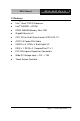
EPIC Board EPIC-9457 Rev.A 1.2 Features ® z Intel Atom™ N270 Processor z Intel 945GSE + ICH7M z DDR2 400/533 Memory, Max. 2GB z Gigabit Ethernet x 2 z CRT, DVI or 24-bit Dual-channel LVDS LCD, TV z AC97 2.0 Codec 2CH Audio z USB2.
EPIC Board EPIC-9457 Rev.A 1.3 Specifications System z Form Factor EPIC Express Board z Processor Onboard Intel Atom™ N270 ® Processor 1.6GHz, FSB: 400/533MHz z System Memory 200-pin DDR2 SODIMM x1, Max.
EPIC Board EPIC-9457 Rev.A z Board Size 4.5" x 6.5" (115mm x 165mm) z Gross Weight 1.1 lb (0.5KG) z Operation Temperature 32°F ~ 140°F (0°C ~ 60°C) or -4°F ~ 158°F (-20°C ~ 70°C) for WiTAS1 z Storage Temperature -40°F ~ 176°F (-40°C ~ 80°C) z Operation Humidity 0% ~ 90% relative humidity, non-condensing Display: Supports CRT/LCD simultaneous/ dual view displays ® z Chipset Intel 945GSE integrated z Memory Shared system memory up to 224MB with DVMT3.
EPIC Board EPIC-9457 Rev.A CompactFlash™ x 1 z Serial Port RS-232 x 3, RS-232/422/485 x 1 z Parallel Port SPP/EPP/ECP Mode z USB USB2.
EPIC Board EPIC-9457 Rev.A Chapter 2 Quick Installation Guide Notice: The Quick Installation Guide is derived from Chapter 2 of user manual. For other chapters and further installation instructions, please refer to the user manual CD-ROM that came with the product. Part No.
EPIC Board EPIC-9457 Rev.A 2.1 Safety Precautions Always completely disconnect the power cord from your board whenever you are working on it. Do not make connections while the power is on, because a sudden rush of power can damage sensitive electronic components. Always ground yourself to remove any static charge before touching the board. Modern electronic devices are very sensitive to static electric charges. Use a grounding wrist strap at all times.
EPIC Board EPIC-9457 Rev.A 2.
EPIC Board Solder Side Chapter 2 Quick Installation Guide 2-4 EPIC-9457 Rev.
EPIC Board EPIC-9457 Rev.
EPIC Board 2.3 Mechanical Drawing Component Side (2 COM ports) Chapter 2 Quick Installation Guide 2-6 EPIC-9457 Rev.
EPIC Board EPIC-9457 Rev.
EPIC Board Component Side (1 COM port) Chapter 2 Quick Installation Guide 2-8 EPIC-9457 Rev.
EPIC Board EPIC-9457 Rev.A 2.4 List of Jumpers The board has a number of jumpers that allow you to configure your system to suit your application.
EPIC Board EPIC-9457 Rev.A 2.5 List of Connectors The board has a number of connectors that allow you to configure your system to suit your application.
EPIC Board EPIC-9457 Rev.
EPIC Board EPIC-9457 Rev.A 2.6 Setting Jumpers You configure your card to match the needs of your application by setting jumpers. A jumper is the simplest kind of electric switch. It consists of two metal pins and a small metal clip (often protected by a plastic cover) that slides over the pins to connect them. To “close” a jumper you connect the pins with the clip. To “open” a jumper you remove the clip. Sometimes a jumper will have three pins, labeled 1, 2 and 3.
EPIC Board EPIC-9457 Rev.A 2.7 VIO Voltage Selection (JP1) JP1 Function 1-2 +5V 2-3 +3.3V (Default) 2.8 24-bit LVDS Operating Voltage Selection (JP2) JP2 Function 1-2 +5V 2-3 +3.3V (Default) 2.9 Clear CMOS (JP3) JP3 Function 1-2 Protected (Default) 2-3 Clear 2.10 24-bit LVDS Inverter Power Selection (JP4) JP4 Function 1-2 +5V (Default) 2-3 +12V 2.11 18-bit LVDS Operating Voltage Selection (JP5) JP5 Function 1-2 +5V 2-3 +3.3V (Default) 2.
EPIC Board 2-3 EPIC-9457 Rev.A +12V 2.13 Touch Screen 4, 5, 8 Wire Selection (JP7) JP7 Function 1-2 4, 8 wire (Default) Open 5 wire 2.14 COM2 Ring/ +5V/ +12V Selection (JP8) JP8 Function 1-2 +12V 3-4 Ring (Default) 5-6 +5V 2.15 AT/ATX Selection (S1) Label Function 1(ON), 2(OFF) ATX (Default) 1(OFF), 2(ON) AT 2.
EPIC Board EPIC-9457 Rev.A 5 IDE LED (+) 6 IDE LED (-) 7 Power LED (+) 8 Power LED (-) 9 Reset Switch (+) 10 Reset Switch (-) 2.17 24-bit Inverter Power Connector (CN2) Pin Signal Pin Signal 1 LCD Inverter Power 2 Backlight Control 3 GND 4 GND 5 Backlight Enable 2.18 24-bit LVDS Connector (CN4) Pin Signal Pin Signal 1 ENBKL 2 N.
EPIC Board EPIC-9457 Rev.A 2.19 Wide Voltage Power Connector (CN5) Pin Signal Pin Signal 1 PGND 2 PGND 3 DC In 4 DC In The minimum power consumption for booting is 25Watts without any connecting device. As this board is design for the lower power consumption, please do not using over 40Watts with all of extra device. If user is not using the power connect from the board for extra device, the above rule is not suitable. 2.
EPIC Board EPIC-9457 Rev.A 11 LVDS1_TX1- 12 LVDS1_TX1+ 13 LVDS1_TX2- 14 LVDS1_TX2+ 15 N.C 16 N.C 17 N.C 18 N.C 19 LVDS2_TX0- 20 LVDS2_TX0+ 21 LVDS2_TX1- 22 LVDS2_TX1+ 23 LVDS2_TX2- 24 LVDS2_TX2+ 25 N.C 26 N.C 27 PPVCC 28 GND 29 LVDS2_TXCLK- 30 LVDS2_TXCLK+ 2.22 18-bit Inverter Power Connector (CN9) Pin Signal Pin Signal 1 LCD Inverter Power 2 Backlight Control 3 GND 4 GND 5 Backlight Enable 2.
EPIC Board EPIC-9457 Rev.A 5 USBD5+ 6 USBD6+ 7 GND 8 USBD6- 9 GND 10 +5V 2.25 LPT Port Connector (CN12) Pin Signal Pin Signal 1 #STROBE 2 #AFD 3 DATA0 4 #ERROR 5 DATA1 6 #INIT 7 DATA2 8 #SLIN 9 DATA3 10 GND 11 DATA4 12 GND 13 DATA5 14 GND 15 DATA6 16 GND 17 DATA7 18 GND 19 #ACK 20 GND 21 BUSY 22 GND 23 PE 24 GND 25 SELECT 26 N.C 2.
EPIC Board EPIC-9457 Rev.A 2.
EPIC Board EPIC-9457 Rev.A 2.29 PS2 Keyboard/Mouse Connector (CN16) Pin Signal Pin Signal 1 KB_DATA 2 KB_CLK 3 GND 4 +5V 5 MS_DATA 6 MS_CLK 2.30 Touch Screen Connector (CN18) Pin 8-wire Signal 4-wire Signal 5-wire Signal 1 2 Ground Top Excite Ground Top Ground UL(Y) 3 Bottom Excite Bottom UR(H) 4 Left Excite Left LL(L) 5 Right Excite Right LR(X) 6 Top Sense N.C SENSE 7 Bottom Sense N.C N.C 8 Left Sense N.C N.C 9 Right Sense N.C N.C 2.
EPIC Board EPIC-9457 Rev.A 2.32 COM1/2 Connectors (CN24) Pin Signal Pin Signal 1 DCD1 2 RXD1 3 TXD1 4 DTR1 5 GND 6 DSR1 7 RTS1 8 CTS1 9 RI1 10 DCD2 (422TXD-/485DATA-) 11 RXD2 (422RXD-) 12 TXD2 (422TXD+/485DATA+) 13 DTR2 (422RXD+) 14 GND 15 DSR2 16 RTS2 17 CTS2 18 RI2/+5V/+12V 2.
EPIC Board EPIC-9457 Rev.A 2.34 Onboard BIOS Programming I/F (CN28) Pin Signal Pin Signal 1 +3.3 Volt. 2 Ground 3 SPI_CE# 4 SPI_CLK 5 SPI_SO 6 SPI_SI 7 N.C 8 N.C 2.35 Primary EIDE Connector (IDE1) Pin Signal Pin Signal 1 IDE RESET 2 GND 3 DATA7 4 DATA8 5 DATA6 6 DATA9 7 DATA5 8 DATA10 9 DATA4 10 DATA11 11 DATA3 12 DATA12 13 DATA2 14 DATA13 15 DATA1 16 DATA14 17 DATA0 18 DATA15 19 GND 20 N.
EPIC Board EPIC-9457 Rev.A 37 CS#1 38 CS#3 39 LED 40 GND 41 +5V 42 +5V 43 GND 44 N.C Note: User can use internal power (CN15) with IDE Device only.
EPIC Board EPIC-9457 Rev.
EPIC Board EPIC-9457 Rev.
EPIC Board 3.1 EPIC-9457 Rev.A System Test and Initialization These routines test and initialize board hardware. If the routines encounter an error during the tests, you will either hear a few short beeps or see an error message on the screen. There are two kinds of errors: fatal and non-fatal. The system can usually continue the boot up sequence with non-fatal errors.
EPIC Board 3.2 EPIC-9457 Rev.A Award BIOS Setup Awards BIOS ROM has a built-in Setup program that allows users to modify the basic system configuration. This type of information is stored in battery-backed CMOS RAM so that it retains the Setup information when the power is turned off. Entering Setup Power on the computer and press immediately. This will allow you to enter Setup. Standard CMOS Features Use this menu for basic system configuration. (Date, time, IDE, etc.
EPIC Board EPIC-9457 Rev.A PnP/PCI Configurations This entry appears if your system supports PnP/PCI. PC Health Status Use this menu to set PC Health Status. Frequency/Voltage Control Use this menu to specify your settings for auto detect DIMM/PCI clock and spread spectrum. Load Optimized Defaults Use this menu to load the BIOS default values that are factory settings for optimal performance system operations.
EPIC Board EPIC-9457 Rev.
EPIC Board EPIC-9457 Rev.A The EPIC-9457 Rev.A comes with a CD-ROM that contains all drivers and utilities that meet your needs. Follow the sequence below to install the drivers: Step 1 – Install INF Update Utility v8.2.0.1014 Driver Step 2 – Install Intel Graphics Media Accelerator Driver Step 3 – Install Intel Ethernet Driver Step 4 – Install Realtek ALC655 Audio Driver v3.71 Step 5 – Install PenMount 6300 Touch Driver USB 2.
EPIC Board EPIC-9457 Rev.A 4.1 Installation: Insert the EPIC-9457 Rev.A CD-ROM into the CD-ROM Drive. And install the drivers from Step 1 to Step 5 in order. Step 1 – Install INF Update Utility v8.2.0.1014 Driver 1. Click on the Step 1 - INF Update Utility v8.2.0.1014 Driver folder and then double click on the Setup.exe 2. Follow the instructions that the window shows 3. The system will help you install the driver automatically Step 2 – Install Intel Graphics Media Accelerator Driver 1.
EPIC Board EPIC-9457 Rev.A v3.71 folder and select the OS folder your system is 2. Double click on the setup.exe file in the OS folder 3. Follow the instructions that the window shows 4. The system will help you install the driver automatically Step 5 – Install PenMount 6300 Touch Driver 1. Click on the Step 5 – PenMount 6300 Touch Driver folder and select the OS folder your system is 2. Double click on the Setup.exe file in the OS folder 3. Follow the instructions that the window shows 4.
EPIC Board EPIC-9457 Rev.
EPIC Board EPIC-9457 Rev.A A.1 Programming EPIC-9457 Rev.A utilizes ITE 8781 chipset as its watchdog timer controller. Below are the procedures to complete its configuration and the AAEON initial watchdog timer program is also attached based on which you can develop customized program to fit your application. Configuring Sequence Description After the hardware reset or power-on reset, the ITE 8781 enters the normal mode with all logical devices disabled except KBC.
EPIC Board EPIC-9457 Rev.A There are three steps to complete the configuration setup: (1) Enter the MB PnP Mode; (2) Modify the data of configuration registers; (3) Exit the MB PnP Mode. Undesired result may occur if the MB PnP Mode is not exited normally. (1) Enter the MB PnP Mode To enter the MB PnP Mode, four special I/O write operations are to be performed during Wait for Key state.
EPIC Board EPIC-9457 Rev.A WatchDog Timer Configuration Registers Configure Control (Index=02h) This register is write only. Its values are not sticky; that is to say, a hardware reset will automatically clear the bits, and does not require the software to clear them.
EPIC Board EPIC-9457 Rev.
EPIC Board EPIC-9457 Rev.A A.2 ITE8781 Watchdog Timer Initial Program .MODEL SMALL .CODE Main: CALL Enter_Configuration_mode CALL Check_Chip mov cl, 7 call Set_Logic_Device ;time setting mov cl, 10 ; 10 Sec dec al Watch_Dog_Setting: ;Timer setting mov al, cl mov cl, 73h call Superio_Set_Reg ;Clear by keyboard or mouse interrupt mov al, 0f0h mov cl, 71h call Superio_Set_Reg ;unit is second.
EPIC Board EPIC-9457 Rev.
EPIC Board EPIC-9457 Rev.
EPIC Board EPIC-9457 Rev.A OUT DX,AL MOV DX,WORD PTR CS:[Cfg_Port+06h] IN AL,DX RET Read_Configuration_Data ENDP Write_Configuration_Data PROC NEAR MOV DX,WORD PTR CS:[Cfg_Port+04h] OUT DX,AL XCHG AL,AH MOV DX,WORD PTR CS:[Cfg_Port+06h] OUT DX,AL RET Write_Configuration_Data ENDP Superio_Set_Reg proc near push ax MOV DX,WORD PTR CS:[Cfg_Port+04h] mov al,cl out dx,al pop ax inc dx out dx,al ret Superio_Set_Reg endp.
EPIC Board Set_Logic_Device proc EPIC-9457 Rev.A near push ax push cx xchg al,cl mov cl,07h call Superio_Set_Reg pop cx pop ax ret Set_Logic_Device endp ;Select 02Eh->Index Port, 02Fh->Data Port Cfg_Port DB 087h,001h,055h,055h DW 02Eh,02Fh END Main Note: Interrupt level mapping 0Fh-Dh: not valid 0Ch: IRQ12 . .
EPIC Board EPIC-9457 Rev.
EPIC Board B.1 I/O Address Map Appendix B I/O Information B-2 EPIC-9457 Rev.
EPIC Board EPIC-9457 Rev.A B.
EPIC Board B.3 IRQ Mapping Chart B.4 DMA Channel Assignments Appendix B I/O Information B-4 EPIC-9457 Rev.
EPIC Board EPIC-9457 Rev.
EPIC Board EPIC-9457 Rev.A C.1 List of Mating Connectors and Cables The table notes mating connectors and available cables.
EPIC Board EPIC-9457 Rev.A compatible) CN12 CN13 CN14 CN15 CN16 CN18 CN19 CN20 CN21 IDE1 2.00mm Pitch 26 pins ( CATCH CATCH H754-2x13 or compatible) (HoBase System Fan 2543-WS-3 or Connector HoBase compatible) 2.