Industrial Motherboard EPC-CV1 Series
E8294 First Edition April 2013 Copyright Notice This document is copyrighted, 2013. All rights are reserved. The original manufacturer reserves the right to make improvements to the products described in this manual at any time without notice. No part of this manual may be reproduced, copied, translated, or transmitted in any form or by any means without the prior written permission of the original manufacturer. Information provided in this manual is intended to be accurate and reliable.
Contents Chapter 1: Product overview 1.1 Package contents.......................................................................... 1-1 1.3 Specifications................................................................................ 1-2 1.2 Features......................................................................................... 1-1 Chapter 2: Motherboard information 2.1 Before you proceed...................................................................... 2-1 2.3 Screw size........
Contents 3.5 Monitor menu................................................................................ 3-9 3.5.1 CPU Temperature / MB Temperature [xxxºC/xxxºF]......... 3-9 3.5.3 Chassis Q-Fan Control [Enabled].................................. 3-10 3.5.2 Chassis Fan Speed [xxxx RPM] or [N/A]......................... 3-9 3.6 3.5.4 Boot menu................................................................................... 3-10 3.6.1 Bootup NumLock State [On].....................................
Chapter 1 Product overview 1.1 Package contents Check your industrial motherboard package for the following items. 1 x Industrial Motherboard 1 x Cable Kit 1 x DVD-ROM for manual (in PDF format) and drivers NOTE: If any of the above items are damaged or missing, contact your distributor or sales representative immediately. 1.
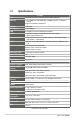
1.3 Specifications CPU Memory Chipset I/O Chipset LAN Audio Expansion slot BIOS H/W Status Monitor Watchdog Timer Smart Fan Control Wake On LAN / PXE Power States Graphics Chipset Graphics Multi Display Resolution LVDS Inverter Control SYSTEM Integrated Intel® Atom™ processor N2600 / N2800 (optional) 1 x SO-DIMM, max.
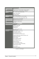
Storage USB Display I/O Audio I/O LAN I/O Serial port PS/2 port DIO Fan RTC I/O 2 x SATA 3Gb/s ports 6 x USB 2.
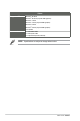
Others Supported OS Windows XP 32-bit ® Windows® XP 64-bit (only with AMD graphics) Windows® 7 32-bit Windows® 7 64-bit (only with AMD graphics) Windows® 8 32-bit Windows® 8 64-bit (only with AMD graphics) Accessories Linux Fedora 1 x SATA 3Gb/s cable 1 x SATA power cable 1 x Support DVD (Drivers, Manual) NOTE: Specifications are subject to change without notice.
Chapter 2 Motherboard information 2.1 Before you proceed Take note of the following precautions before you install motherboard components or change any motherboard settings. CAUTION! • Unplug the power cord from the wall socket before touching any component. • Before handling components, use a grounded wrist strap or touch a safely grounded object or a metal object, such as the power supply case, to avoid damaging them due to static electricity.
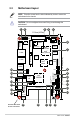
2.2 Motherboard layout NOTE: Place five screws into the holes indicated by circles to secure the motherboard to the chassis. CAUTION! Do not overtighten the screws! Doing so can damage the motherboard. 1 2 3 4 5 11.5cm(4.53in) PCIEX1_1 20 VGA USB1 Intel® N2600 COM4 J1 DDR3 DIMM_A1 EATX_PWR1 19 LVDS_VDD_SEL1 CLRTC1 J2 Super I/O 16.5cm(6.
Connectors/Jumpers/Slots 1. Digital audio connector (4-1 pin SPDIF_OUT1) 2. Line-Out / Mic-In audio connector (10-1 pin AAFP1) 3. SPI programming connector (8-pin SPI1) 4. Audio amplifier connector (4-pin AMP_CON1) 5. Serial ATA 3Gb/s connectors (7-pin SATA3G_1/2) 6. Internal speaker connector (4-pin SPEAKER) 7. LVDS connector (30-pin LVDS1) 8. VGA connector (16-pin VGA) 9. LCD inverter power setting jumper (3-pin LCD_POWER_SEL1) 10. LVDS backlight brightness control jumper (3-pin L_BRIGHTNESS1) 11.
2.3 2.3.
2.3.
2.4 Central Processing Unit (CPU) The motherboard comes with an integrated Intel® Atom™ processor N2600 / N2800 (optional). Integrated Intel® Atom™ processor EPC-CV1 Series Integrated Intel® Atom™ processor 2.5 System memory This motherboard comes with one Double Data Rate 3 (DDR3) Small Outline Dual Inline Memory Modules (SO-DIMM) socket.
To remove a DIMM 3 Chapter 2: Motherboard information 2-7
2.6 1. Jumpers Clear RTC RAM (3-pin CLRTC1) This jumper allows you to clear the Real Time Clock (RTC) RAM in CMOS. You can clear the CMOS memory of date, time, and system setup parameters by erasing the CMOS RTC RAM data. The onboard button cell battery powers the RAM data in CMOS, which include system setup information such as system passwords. 2 3 2 1 CLRTC1 Normal (Default) Clear EPC-CV1 Series Clear CMOS RAM To erase the RTC RAM: 1. Turn OFF the computer and unplug the power cord. 2.
2. COM1 Ring and voltage selection (6-pin J1) J1 1 2 +12V 3 4 +5V 5 6 Ring (Default) EPC-CV1 Series COM1 Ring and voltage selection Pins 3.
4. LVDS backlight brightness control jumper (3-pin L_BRIGHTNESS1) 2 1 L_BRIGHTNESS1 DC MODE (Default) PWM MODE EPC-CV1 Series LVDS backlight brightness control jumper Pins 1-2 DC Mode (Default) 2-3 PWM Mode 5.
6.
2.7 2.7.1 1 1. 2. Connectors Rear panel connectors 2 3 4 5 HDMI port. This port is for a High-Definition Multimedia Interface (HDMI) connector, and is HDCP compliant allowing playback of HD DVD, Blu-Ray, and other protected content. LAN (RJ-45) ports. These ports allow Gigabit connection to a Local Area Network (LAN) through a network hub. Refer to the table below for the LAN port LED indications.
2.7.2 1. Internal connectors Line-Out / Mic-In audio connector (10-1 pin AAFP1) This connector is for Line-Out / Mic-In audio connection. LINE1-JD GND NC MIC1-JD AAFP1 A_MIC1_L A_MIC1_R LINE-R A_JD_FRONT LINE-L PIN 1 EPC-CV1 Series Line-Out / Mic-In audio connector Digital audio connector (4-1 pin SPDIF_OUT1) A_SPDIF_OUT GND This connector is for an additional Sony/Philips Digital Interface (S/PDIF) port.
3. EATX power connector (2-pin EATX_PWR1) This connector is for EATX power supply plug. The power supply plug is designed to fit this connector in only one orientation. Find the proper orientation and push down firmly until the connector completely fit. EATX_PWR1 + - EPC-CV1 Series EATX power connector 4. Serial port connectors [WtoB CON 9P, 1.25mm, S/T, SMT / ACES / 5027300971-001] (9-pin COM2/3/4) These connectors are for serial (COM) ports.
5. Chassis fan connector (4-pin CHA_FAN1) Connect the fan cable to the fan connector on the motherboard, ensuring that the black wire of the cable matches the ground pin of the connector. PWM SENSE VCC GND CHA_FAN1 EPC-CV1 Series Chassis fan connector CAUTION: Do not forget to connect the fan cable to the fan connector. Insufficient air flow inside the system may damage the motherboard components. This is not a jumper! Do not place jumper caps on the fan connector! 6.
7. System panel connector (10-1 pin F_PANEL1) This connector supports several chassis-mounted functions. PIN 1 HD_LED+ HD_LEDGND HWRST# (NC) PLED+ PLEDPANSWH# GND PWR BTN PWR LED RESET +HD_LED F_PANEL1 EPC-CV1 Series System panel connector • • • • 2-16 System power LED (2-pin PWR LED) This 2-pin connector is for the system power LED. Connect the chassis power LED cable to this connector.
8. Serial ATA 3Gb/s connectors (7-pin SATA3G_1/2]) These connectors connect to Serial ATA 3Gb/s hard disk drives and optical drives via Serial ATA 3Gb/s signal cables. GND RSATA_TXP2 RSATA_TXN2 GND RSATA_RXN2 RSATA_RXP2 GND SATA3G_2 GND RSATA_RXP1 RSATA_RXN1 GND RSATA_TXN1 RSATA_TXP1 GND SATA3G_1 EPC-CV1 Series SATA 3.0Gb/s connectors NOTES: 9. • These connectors are set to [IDE] by default. In IDE mode, you can connect Serial ATA boot/data hard disk drives to these connectors.
10. USB 2.0 connector (10-pin USB1) This connector is for USB 2.0 ports. Connect the USB module cable to this connector, then install the module to a slot opening at the back of the system chassis. This USB connector complies with USB 2.0 specification that supports up to 480 Mbps connection speed. USB1 PIN 1 +5V USB4-_R USB4+_R GND GND GND GND USB5+_R USB5-_R +5V EPC-CV1 Series USB 2.0 connector CAUTION! Never connect a 1394 cable to the USB connector.
12. PS/2 keyboard/mouse connector (6-pin KBMS1) This connector is for an IBM PS/2-compatible keyboard or mouse. KBMS1 MS_DATA GND KB_DATA MS_CLK +5V KB_CLK PIN 1 EPC-CV1 Series PS/2 keyboard/mouse connector 13 Backlight inverter power connector [WAFER HD 5P S/T 2.0mm WHITE / PINREX / 721-81-05TW00] (5-pin INV1) Connect the backlight inverter power cable to this connector.
14. VGA connector [BOX HEADER 2X8P S/T 2.0mm SMT // PINREX / 52M-9016GBE0] (16-pin VGA) This 16-pin connector is for a VGA monitor or other VGA-compatible devices. VGA PIN 1 +5V GND NC RDDCA_DATA_R R_HSYNC R_VSYNC RDDCA_CLK_R GND DAC_R DAC_G DAC_B NC GND NC GND GND EPC-CV1 Series VGA connector 15. A udio amplifier connector [WtoB CON 4P, 1.25mm, S/T, SMT // ACES / 85025-04701] (4-pin AMP_CON1) This connector is for an external audio amplifier.
16. LVDS connector [WtoB CON 2P, 1.25mm, R/A, SMT // ACES / 8520402001] (30-pin LVDS1) This connector is for an LCD monitor that supports Low-voltage differential signaling (LVDS) interface.
18. Digital I/O connector (10-pin DIO1) This connector includes 8 I/O lines. All of the Digital I/O lines are programmable and each I/O pin can be individually programmed to support various devices. DIO1 PIN 1 DIO_P#1 (GPIO80) DIO_P#3 (GPIO82) DIO_P#5 (GPIO84) DIO_P#7 (GPIO86) +5V DIO_P#2 (GPIO81) DIO_P#4 (GPIO83) DIO_P#6 (GPIO85) DIO_P#8 (GPIO87) GND EPC-CV1 Series Digital I/O connector NOTE: To configure the I/O pins in BIOS, go to the Advanced tab > DIO Function > GPIO 1~8. See section 3.4.
Chapter 3 BIOS setup 3.1 BIOS setup program Use the BIOS Setup program to update the BIOS or configure its parameters. The BIOS screens include navigation keys and brief online help to guide you in using the BIOS Setup program. Entering BIOS Setup at startup To enter BIOS Setup at startup: • Press during the Power-On Self Test (POST). If you do not press , POST continues with its routines.
3.2 BIOS menu screen Menu items Menu bar General help Configuration fields BIOS Information BIOS Version Build Date 0202 x64 11/30/2012 CPU Information Intel(R) Atom(TM) CPU 600 @ 1.
Menu items The highlighted item on the menu bar displays the specific items for that menu. For example, selecting Main shows the Main menu items. The other items (Ai Tweaker, Advanced, Monitor, Boot, Tool, and Exit) on the menu bar have their respective menu items. Back button This button appears when entering a submenu. Press or use the USB mouse to click this button to return to the previous menu screen.
3.3 Main menu The Main menu screen appears when you enter the Advanced Mode of the BIOS Setup program. The Main menu provides you an overview of the basic system information, and allows you to set the system date, time, language, and security settings. BIOS Information BIOS Version Build Date 0202 x64 11/30/2012 CPU Information Intel(R) Atom(TM) CPU 600 @ 1.
Administrator Password If you have set an administrator password, we recommend that you enter the administrator password for accessing the system. Otherwise, you might be able to see or change only selected fields in the BIOS setup program. To set an administrator password: 1. Select the Administrator Password item and press . 2. From the Create New Password box, key in a password, then press . 3. Confirm the password when prompted. To change an administrator password: 1. 2.
3.4 Advanced menu The Advanced menu items allow you to change the settings for the CPU and other system devices. CAUTION: Be cautious when changing the settings of the Advanced menu items. Incorrect field values can cause the system to malfunction. CPU Configuration Parameters > CPU Configuration > IDE Configuration > USB Configuration > APM > Panel Controller > DIO Function > North Bridge LVDS Config Select > Onboard Devices Configuration 3.4.
3.4.2 IDE Configuration While entering Setup, the BIOS automatically detects the presence of SATA devices. The SATA Port items show Not Present if no SATA device is installed to the corresponding SATA port. SATA Controller(s) [Enabled] [Disabled] [Enabled] Disables the onboard SATA controllers. Enables the onboard SATA controllers. Configure SATA as [IDE] Allows you to set the SATA configuration.
Power On By Ring [Disabled] [Disabled] [Enabled] 3.4.5 Disables Ring to generate a wake event. Enables Ring to generate a wake event. Panel Controller (AMD® GPU only) Backlight Brightness Setting [75] Allows you to set the backlight brightness. Select a larger number for a brighter backlight. Configuration options: [0] [25] [50] [75] [100] 3.4.6 DIO Function GPIO 1~8 [Input] Allows you to configure the digital signal of the GPIO (General Purpose Input/ Output) pins 1~8.
Onboard LAN Boot ROM [Disabled] This item appears only when you set the Onboard LAN item to [Enabled] and allows you to enable or disable the Boot ROM of the onboard LAN controller. Configuration options: [Enabled] [Disabled] 3.5 Monitor menu The Monitor menu displays the system temperature/power status, and allows you to change the fan settings. 3.5.1 CPU Temperature / MB Temperature [xxxºC/xxxºF] The onboard hardware monitor automatically detects and displays the CPU and motherboard temperatures.
3.5.3 [Disabled] [Enabled] Chassis Q-Fan Control [Enabled] Disables the Chassis Q-Fan control feature. Enables the Chassis Q-Fan control feature. Chassis Fan Profile [Standard] This item appears only when you enable the Chassis Q-Fan Control feature and allows you to set the appropriate performance level of the chassis fan. [Standard] Sets to [Standard] to make the chassis fan automatically adjust depending on the chassis temperature.
3.6.2 [Enabled] Full Screen Logo [Disabled] Enables the full screen logo display feature. [Disabled] Disables the full screen logo display feature. 3.6.3 Wait for ‘F1’ If Error [Enabled] 3.6.4 Boot Option Priorities When this item is set to [Enabled], the system waits for the F1 key to be pressed when error occurs. Configuration options: [Disabled] [Enabled] These items specify the boot device priority sequence from the available devices.
3.8 Exit menu The Exit menu items allow you to load the optimal default values for the BIOS items, and save or discard your changes to the BIOS items. You can access the EZ Mode from the Exit menu. Load Optimized Defaults This option allows you to load the default values for each of the parameters on the Setup menus. When you select this option or if you press , a confirmation window appears. Select Yes to load the default values.
Appendix Notices Federal Communications Commission Statement This device complies with Part 15 of the FCC Rules. Operation is subject to the following two conditions: • This device may not cause harmful interference. • This device must accept any interference received including interference that may cause undesired operation. This equipment has been tested and found to comply with the limits for a Class A digital device, pursuant to Part 15 of the FCC Rules.
電子信息產品污染控制標示:圖中之數字為產品之環保使用期限。僅 指電子信息產品中含有的有毒有害物質或元素不致發生外洩或突變從 而對環境造成污染或對人身、財產造成嚴重損害的期限。 有毒有害物質或元素的 名 稱 及 含 量 說 明 標 示 : 有害物質或元素 部件名稱 鉛 (Pb) 汞 (Hg) 鎘 (Cd) 六 價 鉻 (Cr(VI)) 多 溴 聯 苯 (PBB) 多溴二苯醚 (PBDE) 印刷電路板及其 電子組件 × ○ ○ ○ ○ ○ 外部信號連接頭 及線材 × ○ ○ ○ ○ ○ ○: 表示該有毒有害物質在該部件所有均質材料中的含量均在 SJ/T 11363-2006 標准規定的限量要求以下。 ×: 表示該有毒有害物質至少在該部件的某一均質材料中的含量超出 SJ/T 11363-2006 標准規定的限量要求,然該部件仍符合歐盟指令 2002/95/EC 的 規范。 備註:此產品所標示之環保使用期限,係指在一般正常使用狀況下。 A-2 EPC-CV1